Advertisement
Quick Links
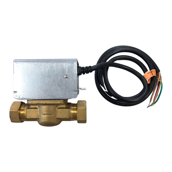
V4043, V4044 Valves;
V8043, V8044 Zone Valves
APPLICATION
These valves consist of an actuator motor and valve
assembly for controlling the flow of hot and/or cold water.
The V4043 and V8043 provide two-position, straight-
through control of supply water. The V4044 and V8044
provide two-position, diverting control of supply water.
The valves are designed for use with fan coil and other
units requiring quiet, compact water valves. The V8043E
and F also control supply water for baseboard radiators
and convectors. The V4043E and V8043J provide
straight-through control of steam only. Models are
available with 125 or 300 psi operating pressure.
INSTALLATION
When Installing this Product...
1. Read these instructions carefully. Failure to follow
them could damage the product or cause a hazard-
ous condition.
2. Check the ratings given in the instructions and on
the product to make sure the product is suitable for
your application.
3. Installer must be a trained, experienced service
technician.
4. After installation is complete, check out product
operation as provided in these instructions
CAUTION
1.
Disconnect power supply before connecting
wiring to prevent electrical shock of equip-
ment damage.
2.
Normally it is not necessary to remove the
powerhead from the valve body during instal-
lation. If the valve must be disassembled, be
certain that it is reassembled with the water
INSTALLATION INSTRUCTIONS
flow in the direction of the arrow. Reversal of
the powerhead will result in damage to the
gear train.
3.
On 24V systems, never jumper the valve coil
terminals even temporarily. This may burn
out the heat anticipator in the thermostat.
IMPORTANT
Use this valve in hydronic heating systems
which do not contain dissolved oxygen in the
system water. The dissolved oxygen, which is
found in systems that have a frequent source of
makeup water, causes the rubber plug inside
the valve to deteriorate and eventually fail.
LOCATION
Install the valve in an area with adequate clearance to:
— Move the manual opening lever on the side of the
powerhead.
— Remove the powerhead cover.
— Wire the powerhead.
— Replace the powerhead motor.
The valve location should be in an area where the
temperature does not exceed the maximum valve
operating temperature as shown in Fig. 1. The maximum
valve operating temperature depends on the maximum
ambient temperature at the valve location and the
maximum fluid temperature. Using the graph in Fig. 1,
the maximum valve operating temperature can be found
as follows:
1. Measure ambient temperature at valve and locate
this temperature on the ambient temperature scale
on the graph.
2. Draw a line from this ambient temperature, parallel
with the fluid temperature scale, to the maximum
fluid temperature line.
3. Draw a line from this point down to the fluid temp-
erature scale to find maximum operating tempera-
ture. (Note the example, shown by the dashed line
in Fig. 1).
Place Bar Code Here
95-6983-11
Advertisement

Related Manuals for Honeywell V4044


Summarization of Contents
APPLICATION
Product Overview
Describes the function and types of Honeywell V4043, V4044, V8043, V8044 zone valves for controlling water flow.
INSTALLATION
Installation Precautions
Key instructions for installers before beginning product installation, emphasizing safety and careful reading.
Electrical Safety
Warning regarding disconnecting power supply before wiring to prevent electrical shock or damage.
Installation Instructions
Provides step-by-step guidance for installing the valves, including wiring and system considerations.
System Water Quality Requirement
Advises using the valve only in hydronic systems without dissolved oxygen to prevent rubber plug deterioration.
Installation Location and Temperature Limits
Specifies installing the valve in an area with adequate clearance and near temperature limits.
Mounting Guidelines
Details on how to mount the valve in vertical or horizontal piping, ensuring proper orientation and clearance.
Inlet and Outlet Ports Identification
Identifies inlet and outlet ports on straight-through and diverting valves for correct connection.
Flare Fitting Installation
Instructions for installing flare fitting models, emphasizing proper pipe preparation and fittings.
Sweat Copper Fitting Installation
Steps for installing sweat copper models, including pipe preparation and using manual opening lever during soldering.
Sweat Copper Fitting Soldering Precautions
Precautions for soldering sweat copper fittings, advising against silver solder and emphasizing keeping surfaces free of solder.
To Install Replacement Powerhead
Replacing Powerhead on Old Style Bodies
Procedure for replacing powerheads on series 1-5 valve bodies using a conversion kit.
System Drainage for Powerhead Replacement
Notes that system drainage is necessary before powerhead conversion, but not body removal.
Old Style Body Powerhead Removal
Steps to remove the old powerhead from series 1-5 valve bodies, including disconnecting power and draining the system.
Installing Conversion Kit for Old Style Bodies
Instructions for installing the 40003918 conversion kit with brass or composite adapter plates.
Install New Powerhead (Series 1-5)
Steps for attaching the new powerhead to the converted old style valve body, ensuring correct alignment.
SYSTEMS WITH NEW STYLE VALVE BODIES (SERIES 6)
System Drainage for New Style Bodies
Notes that system drainage is not required for new style bodies if the valve body remains in the pipeline.
Remove Old Powerhead (Series 6)
Procedure to remove the old powerhead from series 6 valve bodies, including disconnecting power and wiring.
Install New Powerhead (Series 6)
Steps for attaching the new powerhead to the new style valve body, ensuring correct alignment and securing.
WIRING
Wiring Precautions
Warning to disconnect power before wiring and compliance with local codes for all connections.
Typical Wiring Diagrams
Illustrates typical wiring for V8043E, V8044E, and V8043F valves with thermostats and other components.
T822 Thermostat and V8043A Hookup
Wiring diagram showing connection of T822 thermostat to V8043A valve for heating applications.
T822 Thermostat and V8043E Hookup (No Domestic Hot Water)
Wiring diagram for T822 thermostat and V8043E valve for gas or oil systems without domestic hot water.
T822 Thermostat and V8043E Hookup (With Domestic Hot Water)
Wiring diagram for T822 thermostat and V8043E valve for gas or oil systems with domestic hot water.
V4044/V8044 Wiring with Aquastat
Wiring diagram for V4044 and V8044 valves using an Aquastat changeover control for heating/cooling.
Typical 3-Zone System Wiring
Diagram illustrating a typical 3-zone system using AT87A transformer to power multiple zone valves.
Typical 4-Zone System Wiring
Diagram showing a typical 4-zone system, utilizing W775A panel for multiple zone valves.
Typical 5-Zone System Wiring
Diagram illustrating a typical 5-zone system, using AT87A transformer to power multiple zone valves.
How to Replace a Taco 3-Wire Valve with a Honeywell 2-Wire Valve
Existing Taco System Wiring
Diagram of an existing Taco 3-wire system, identifying wires for correspondence to Honeywell valve wiring.
Wiring Honeywell V8043E to Taco System
Instructions for wiring a Honeywell V8043E to an existing Taco 3-wire system.
How to Replace a Dole 3-Wire Valve with a Honeywell 2-Wire Valve
Existing Dole System Wiring
Diagram of an existing Dole 3-wire system, identifying wires for correspondence to Honeywell valve wiring.
Wiring Honeywell V8043E to Dole System
Instructions for wiring a Honeywell V8043E to an existing Dole 3-wire system.
How to Replace a Flair 3-Wire Valve with a Honeywell 2-Wire Valve
Existing Flair System Wiring
Diagram of an existing Flair 3-wire system, identifying wires for correspondence to Honeywell valve wiring.
Wiring Honeywell V8043E to Flair System
Instructions for wiring a Honeywell V8043E to an existing Flair 3-wire system.
How to Replace a White-Rodgers 3-Wire Valve with a Honeywell 2-Wire Valve
Existing White-Rodgers System
Diagram of an existing White-Rodgers system, identifying wires for correspondence to Honeywell valve wiring.
Wiring Honeywell V8043E to White-Rodgers System
Instructions for wiring a Honeywell V8043E to an existing White-Rodgers system.
Wiring Honeywell V8043F to White-Rodgers System (one option)
Instructions for wiring a Honeywell V8043F to a White-Rodgers system (one option).
Wiring Honeywell V8043F to White-Rodgers System (alternate option)
Instructions for wiring a Honeywell V8043F to a White-Rodgers system (alternate option).
Need help?
Do you have a question about the V4044 and is the answer not in the manual?
Questions and answers