Yamaha PianoCraft RX-E810 Service Manual
Hide thumbs
Also See for PianoCraft RX-E810:
- Owner's manual (74 pages) ,
- Owner's manual (548 pages) ,
- Specifications (2 pages)
Table of Contents
Advertisement
MICRO COMPONENT SYSTEM
RX-E810/RX-E410/
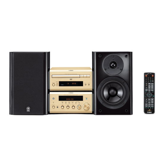
The MCR-E810 is composed of the RX-E810, NX-E800 and DVD-E810.
The MCR-E410 is composed of the RX-E410, NX-E800 and CDX-E410.
This service manual is for the RX-E810, RX-E410 and NX-E800.
For service manual of the DVD-E810 and CDX-E410, please refer to the following publication number:
This manual has been provided for the use of authorized YAMAHA Retailers and their service personnel.
It has been assumed that basic service procedures inherent to the industry, and more specifically YAMAHA Products, are
already known and understood by the users, and have therefore not been restated.
WARNING:
IMPORTANT:
The data provided is believed to be accurate and applicable to the unit(s) indicated on the cover. The research, engineering,
and service departments of YAMAHA are continually striving to improve YAMAHA products. Modifications are, therefore,
inevitable and specifications are subject to change without notice or obligation to retrofit. Should any discrepancy appear to
exist, please contact the distributor's Service Division.
WARNING:
IMPORTANT:
I CONTENTS
TO SERVICE PERSONNEL . . . . . . . . . . . . . . . . . . . . 2
SYSTEM COMPOSITION . . . . . . . . . . . . . . . . . . . . . . 3
FRONT PANELS . . . . . . . . . . . . . . . . . . . . . . . . . . . . . 4
REAR PANELS . . . . . . . . . . . . . . . . . . . . . . . . . . . . 4–6
REMOTE CONTROL PANELS . . . . . . . . . . . . . . . . . . 6
SPECIFICATIONS . . . . . . . . . . . . . . . . . . . . . . . . . . . . 7
INTERNAL VIEW . . . . . . . . . . . . . . . . . . . . . . . . . . . . . 8
DISASSEMBLY PROCEDURES . . . . . . . . . . . . . . . . . 8
SELF DIAGNOSIS FUNCTION (DIAG) . . . . . . . . . 9–15
AMP ADJUSTMENTS . . . . . . . . . . . . . . . . . . . . . . . . 16
1 0 1 0 1 9
DVD-E810
CDX-E410
IMPORTANT NOTICE
Failure to follow appropriate service and safety procedures when servicing this product may result in per-
sonal injury, destruction of expensive components, and failure of the product to perform as specified. For
these reasons, we advise all YAMAHA product owners that any service required should be performed by
an authorized YAMAHA Retailer or the appointed service representative.
The presentation or sale of this manual to any individual or firm does not constitute authorization, certifica-
tion or recognition of any applicable technical capabilities, or establish a principle-agent relationship of
any form.
Static discharges can destroy expensive components. Discharge any static electricity your body may have
accumulated by grounding yourself to the ground buss in the unit (heavy gauge black wires connect to this
buss).
Turn the unit OFF during disassembly and part replacement. Recheck all work before you apply power to
the unit.
2006
This manual is copyrighted by YAMAHA and may not be copied or
redistributed either in print or electronically without permission.
MCR-E810/MCR-E410
SERVICE MANUAL
SERVICE MANUAL
101017
101018
DISPLAY DATA . . . . . . . . . . . . . . . . . . . . . . . . . . . . . 17
IC DATA . . . . . . . . . . . . . . . . . . . . . . . . . . . . . . . . 18–22
BLOCK DIAGRAMS . . . . . . . . . . . . . . . . . . . . . . 23–24
PRINTED CIRCUIT BOARDS . . . . . . . . . . . . . . . 25–31
PIN CONNECTION DIAGRAMS . . . . . . . . . . . . . . . . 32
SCHEMATIC DIAGRAMS . . . . . . . . . . . . . . . . . . 33–37
REPLACEMENT PARTS LIST . . . . . . . . . . . . . . 39–48
REMOTE CONTROLS . . . . . . . . . . . . . . . . . . . . . 49–50
SYSTEM CONTROL . . . . . . . . . . . . . . . . . . . . . . 51–58
All rights reserved.
NX-E800
P.O.Box 1, Hamamatsu, Japan
'06.07
Advertisement
Table of Contents

Related Manuals for Yamaha PianoCraft RX-E810


Summarization of Contents
To Service Personnel
Critical Components Information
Information on components with special characteristics requiring exact replacement.
Leakage Current Measurement
Verification of insulation for exposed conductive surfaces after service.
System Composition
MCR-E810 System Overview
Comprises DVD-E810, RX-E810, and NX-E800 units.
MCR-E410 System Overview
Comprises CDX-E410, RX-E410, and NX-E800 units.
Front Panels
RX-E810 Front Panel Layout
Description of the front panel layout for RX-E810.
RX-E410 Front Panel Layout
Description of the front panel layout for RX-E410.
NX-E800 Speaker Unit
Image of the NX-E800 speaker unit.
Rear Panels
RX-E810 Rear Panel (U, C Models)
Rear panel connections for RX-E810 (U, C).
RX-E810 Rear Panel (T Model)
Rear panel connections for RX-E810 (T).
RX-E810 Rear Panel (K Model)
Rear panel connections for RX-E810 (K).
RX-E810 Rear Panel (A Model)
Rear panel connections for RX-E810 (A).
RX-E810 Rear Panel (B Model)
Rear panel connections for RX-E810 (B).
RX-E410 Rear Panel (B Model)
Rear panel connections for RX-E410 (B).
RX-E810 Rear Panel (G Model)
Rear panel connections for RX-E810 (G).
RX-E410 Rear Panel (G Model)
Rear panel connections for RX-E410 (G).
RX-E810 Rear Panel (L Model)
Rear panel connections for RX-E810 (L).
RX-E810 Rear Panel (V Model)
Rear panel connections for RX-E810 (V).
Remote Control Panels
RX-E810 Remote Control Layout (U, C, T, K, A, L, V)
Layout of the remote control for RX-E810 (U, C, T, K, A, L, V).
RX-E810 Remote Control Layout (B, G)
Layout of the remote control for RX-E810 (B, G).
RX-E410 Remote Control Layout (B, G)
Layout of the remote control for RX-E410 (B, G).
Specifications
Audio Section Specifications
Detailed audio output, input, and performance specifications.
FM Section Specifications
FM tuning range, sensitivity, and signal-to-noise ratio.
AM Section Specifications
AM tuning range and antenna input details.
Speaker Section Specifications (NX-E800)
Speaker type, driver, impedance, and dimensions.
General Specifications
Power supply, accessories, dimensions, and weight.
Internal View
Internal Component Layout
Diagram showing the internal placement of PCBs and components.
Disassembly Procedures
Top Cover Removal
Steps for removing the top cover of the unit.
Front Panel Removal
Steps for removing the front panel assembly.
Self Diagnosis Function (DIAG)
DIAG Menu Items and Sub-menus
List of 9 diagnostic menu items and their sub-menus.
Starting DIAG Procedure
How to initiate the self-diagnosis mode.
Starting DIAG in Protection Cancel Mode
Procedure to enter DIAG mode with protection functions disabled.
Canceling DIAG
Steps to exit DIAG mode and restore factory settings.
Display Information When DIAG Started
What is shown on the display when DIAG mode begins.
Protection Function History
How protection history is stored, cleared, and its significance.
DIAG Menu and Sub-Menu Navigation
Methods for navigating DIAG menus and sub-menus using unit controls.
Functions Available in DIAG Mode
Additional functions like input selection and muting available during diagnosis.
Initial Settings for DIAG
Default settings applied when starting DIAG and restored upon cancellation.
Firmware Version Check
Firmware Version and Checksum Display
Displays firmware version, model, destination, and checksum.
Display Section Check
FL Display Segment and Pattern Check
Program to check the FL display section's segments and patterns.
Factory Preset Initialization
Factory Preset Initialization Options
Options for inhibiting or reserving initialization of backup RAM.
AD Data Check and Protection Functions
Displays A/D conversion values for panel keys and protection detections.
System Status and Control Checks
System Status Voltage Check
Displays voltage status of IC200 pin 92 relative to 5V/500 standard.
Destination Display
Shows the destination of the unit, related to AD port pull-up resistance.
Panel Key (K0/K1) A/D Value Check
Checks A/D values of panel keys for proper operation.
iPod Dock Loop Back Check
Checks iPod dock connectivity by shorting specific pins.
iPod Dock Status
Displays status of iPod accessory power and installation detection.
Protection and Mute Functions
Protection History Display
Displays up to four protection history entries.
Protection History Reset
Initializes the protection history, with options for display or reset.
Mute Function Control
Controls mute status for speakers (SP) and headphones (HP).
Power Off Factor History
Shows up to five past factors that caused the unit to turn off.
Amp Adjustments
Idling Current Confirmation
Procedure for confirming and adjusting idling current for amplifier sections.
Display Data
V501 Display Part Number
Part number and type of the FL display module.
Pin Connection Diagram
Pin assignments for various connectors and components.
Grid Assignment
Assigns grid numbers to display segments and functions.
Anode Connection Details
Maps anode connections to specific display segments and functions.
IC Data
IC200 Microprocessor (M30620MCP-A41FP) Pin Information
Detailed pin descriptions and functions for the microprocessor IC.
IC200 Microprocessor Functional Blocks
Overview of internal peripheral functions and blocks within the microprocessor.
IC200 Microprocessor Pin Function Details
Comprehensive list of pin assignments and their functions for IC200.
IC200 Microprocessor Pin Function Details (Continued)
Further pin assignments and functions for the IC200 microprocessor.
Ket Input (A-D) Pull-up Resistance
Details pull-up resistance for ket input (A-D) measurements.
Destination for AD Port Pull-up Resistance
Specifies pull-up resistance for AD port destination identification.
IC501 FL Display Driver (M66003-0131FP) Pin Information
Pin information and layout for the FL display driver IC501.
IC501 FL Display Driver Functional Blocks
Diagram of functional blocks within the FL display driver IC.
IC501 FL Display Driver Pin Function Details
Detailed pin assignments and functions for the FL display driver IC501.
Block Diagrams
Audio Section Block Diagram
Overall block diagram of the audio signal path and processing.
Power Section Block Diagram
Block diagram illustrating the power supply and distribution circuits.
Printed Circuit Boards
Operation (1) P.C.B. (Side A) Layout
Component layout for the Operation (1) PCB, side A.
Operation (1) P.C.B. (Side B) Layout
Component layout for the Operation (1) PCB, side B.
Operation (2) P.C.B. (Side A) Layout
Component layout for the Operation (2) PCB, side A.
Operation (2) P.C.B. (Side B) Layout
Component layout for the Operation (2) PCB, side B.
Main (1) P.C.B. (Side A) Layout
Component layout for the Main (1) PCB, side A.
Main (1) P.C.B. (Side B) Layout
Component layout for the Main (1) PCB, side B.
Main (2) P.C.B. (Side A) Layout
Component layout for the Main (2) PCB, side A.
Main (3) P.C.B. (Side A) Layout
Component layout for the Main (3) PCB, side A.
Main (4) P.C.B. (Side A) Layout
Component layout for the Main (4) PCB, side A.
Main (2) P.C.B. (Side B) Layout
Component layout for the Main (2) PCB, side B.
Main (4) P.C.B. (Side B) Layout
Component layout for the Main (4) PCB, side B.
Input (1) P.C.B. (Side A) Layout
Component layout for the Input (1) PCB, side A.
Input (1) P.C.B. (Side B) Layout
Component layout for the Input (1) PCB, side B.
Input (2) P.C.B. (Side A) Layout
Component layout for the Input (2) PCB, side A.
Input (2) P.C.B. (Side B) Layout
Component layout for the Input (2) PCB, side B.
Pin Connection Diagrams
IC Pin Connection Diagrams
Diagrams showing pin connections for various integrated circuits.
Diode Pin Connection Diagrams
Pin connections for different types of diodes.
Transistor Pin Connection Diagrams
Pin connections for various transistors.
Schematic Diagrams
Operation Schematic Diagram
Schematic for the Operation (1) and (2) sections, including FL driver.
Operation Schematic Diagram (Continued)
Schematic for Operation 2/2, showing iPod interface and related components.
Main Schematic Diagram
Schematic for Main (1) section, covering HP Amp and Power Amp circuits.
Main Schematic Diagram (Continued)
Schematic for Main (2) and Main (3) sections, including power transformer and master volume.
Input Schematic Diagram
Schematics for Input circuits, including microprocessor and tuner interface.
Replacement Parts List
Electrical Component Parts List
Comprehensive list of electrical components with part numbers and descriptions.
P.C.B. Operation Parts List
Parts list specific to the Operation Printed Circuit Boards.
P.C.B. Main Parts List
Parts list for the Main Printed Circuit Boards.
P.C.B. Main and Input Parts List
Combined parts list for Main and Input PCBs, including resistors and relays.
P.C.B. Input Parts List
Parts list specific to the Input Printed Circuit Boards.
Chip Resistors List
Details on chip resistors, including their part numbers and specifications.
Carbon Resistors List
List of carbon resistors with values, part numbers, and wattage.
RX-E810/RX-E410 Overall Assembly Diagram
Exploded view showing the assembly of the main unit components.
RX-E810/RX-E410 Overall Assy. Parts List
Parts list corresponding to the overall assembly diagram for RX-E810/RX-E410.
NX-E800 Overall Assembly Diagram
Exploded view showing the assembly of the NX-E800 speaker unit.
Remote Control WH217700: RX-E810
RX-E810 Remote Control Schematic
Schematic diagram of the RX-E810 remote control unit.
RX-E810 Remote Control Key Layout
Visual layout of the keys on the RX-E810 remote control.
RX-E810 Remote Control Key Codes
Table mapping remote control keys to their common, DVD/CD, and TUNER codes.
Remote Control WH256400: RX-E410
RX-E410 Remote Control Schematic
Schematic diagram of the RX-E410 remote control unit.
RX-E410 Remote Control Key Layout
Visual layout of the keys on the RX-E410 remote control.
RX-E410 Remote Control Key Codes
Table mapping remote control keys to their custom data codes.
System Control
External Bus Physical Format
Describes the physical composition of the external bus as two bus lines.
RX Command Format
Explains the format of RX commands for DVD/CD units and operation codes.
State Information Format
Details how state information of CD/DVD is expressed via DC voltage levels.
State Information Examples
Provides examples of state information transitions for processes like play, stop, and standby.
RX Request Command Codes
Table listing RX request command codes for DVD and CD units and their functions.
Operation Key Code Transmission
Explains how operation key codes are transmitted from RX to DVD/CD units.
Command Communication: Power On (RX Standby/ON Key)
Sequence diagram for system power-on using the RX "STANDBY/ON" key.
Command Communication: Power On (Individual Unit)
Sequence diagram for individual unit power-on via their "STANDBY/ON" keys.
Command Communication: Timer Function (Timer Play)
Sequence diagram for timer play function, showing state transitions.
Command Communication: System Standby (Power Off)
Sequence diagram for system standby initiated by the RX "STANDBY/ON" key.
Command Communication: Unit Standby (Power Off)
Sequence diagram for individual unit standby via their "STANDBY/ON" keys.
Command Communication: Auto Standby (Power Off)
Sequence diagram for automatic system power-off based on conditions.
Display Control: Display Dimmer Function
How RX controls the DVD/CD display brightness using DIMMER commands.
Display Control: Turn Off VFD
Function to turn off the VFD display using VFD_OFF commands.
Need help?
Do you have a question about the PianoCraft RX-E810 and is the answer not in the manual?
Questions and answers