Table of Contents
Advertisement
SLV-SE610/SE710/SE810/SX710/SX717/SX810/X9
QQ
3 7 63 1515 0
RMT-V259/V259B/V259K/V259L/V259R/V259S/V288/V288A/V288B/V288C
SERVICE MANUAL
SR MECHANISM
• Refer to the SERVICE MANUAL of VHS MECHANICAL
TE
L 13942296513
ADJUSTMENTS VI for MECHANICAL ADJUSTMENTS.
(9-921-647-11)
* The abbreviations of SE610, SE710, SE810, SX710, SX717, SX810 and
X9 contained in this service manual are indicated when these models are
common to all their corresponding models as given below.
Abbreviated
SE610
model name
SE610A
All model
SE610B
names
SE610E
SE610G
SLV-
SE610K
SE610N
www
.
http://www.xiaoyu163.com
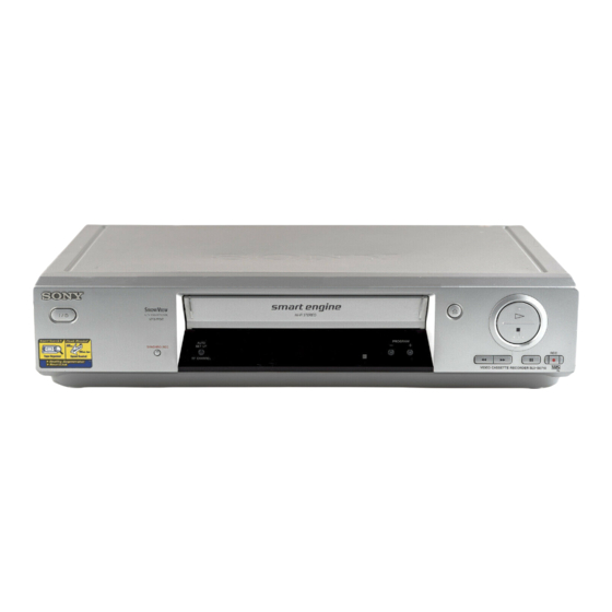
Photo: SLV-SE810
SE710
SE810
SX710
SE710B
SE810B
SX710B
SE710D
SE810D
SX710D
SE710E
SE810E
SX710E
SE710G
SE810G
SX710K
SE710I
SE810K
SX710N
SE710K
SE810N
SE710N
x
ao
u163
y
i
http://www.xiaoyu163.com
2 9
8
Q Q
3
6 7
1 3
1 5
SX717
SX810
X9
SX717D
SX810D
X9B
SX717E
X9D
X9E
X9G
X9N
VIDEO CASSETTE RECORDER
co
.
9 4
2 8
French Model
SLV-SE610B/SE710B/SE810B/
German Model
SLV-SE710D/SE810D/SX710D/
SX717D/SX810D/X9D
Italian Model
East European Model
Russian Model
SLV-SE610K/SE610N/SE710K/SE710N/
SE810K/SE810N/SX710K/SX710N/X9N
North European Model
SLV-SE610E/SE710E/SE810E/
SX710E/SX717E/X9E
UK Model
SLV-SE610G/SE710G/
SE710I/SE810G/X9G
0 5
8
2 9
9 4
2 8
m
9 9
SX710B/X9B
SLV-SE610A
9 9
Advertisement
Table of Contents

Summarization of Contents
Section 1 General Overview
Getting Started
Initial steps for using the VCR, including setup and controls.
Index to Parts and Controls
Identification of front and rear panel components and their functions.
Setting Up the Remote Commander
Remote Control TV Codes
List of manufacturer codes for controlling other TV brands with the remote.
Basic Operations
Playing a Tape
How to play back tapes, including controls and playback options.
Recording TV Programmes
Steps for recording television programs, including timer settings.
Adjusting Picture Quality
Adjusting Tape Tracking
Manual adjustment of tape tracking for optimal picture quality.
Reality Regenerator (RR) Function
Explanation of the RR function for automatic picture restoration.
Section 2 Disassembly
2-1. Upper Case Removal
Step-by-step guide to remove the VCR's top cover.
2-2. Rear Panel Removal
Step-by-step guide to remove the rear panel.
2-3. Power Block Removal
Procedure to remove the power supply unit.
2-4. Front Panel Section Removal
Procedure to remove the front panel assembly.
Section 3 Block Diagrams
3-1. Overall Block Diagram
A high-level overview of the VCR's main functional blocks.
Section 4 Printed Wiring Boards
4-1. Frame Schematic Diagram
Overall schematic showing the interconnection of major boards.
Section 5 Interface Descriptions
5-1. Video Block Interface
Pin functions for the video block interface of IC162.
5-2. Servo Peripheral Circuit Interface
Pin functions for the servo peripheral interface of IC162.
Section 6 Error Codes
6-1. Error Code Indication
How error codes are displayed and a table of common error codes.
Section 7 Adjustments
7-1. Mechanical Adjustments
Reference to external manual for mechanical adjustments.
7-2. Electrical Adjustments
Preparations and procedures for electrical circuit adjustments.
Audio System Adjustments
AF Switching Position Adjustment
Adjusting AF switching for optimal tape interchangeability.
Frequency Response Check
Verifying the audio frequency response characteristics.
Normal Audio System Adjustment
ACE Head Adjustment
Adjusting the ACE head for optimal performance.
E-E Output Level Check
Verifying output levels against reference for E-E signal.
Frequency Response Check
Verifying frequency response characteristics.
Overall Level Characteristic and Distortion Factor Check
Checking record/play levels and distortion against reference.
Overall S/N Check
Confirming the signal-to-noise ratio meets specifications.
Section 8 Repair Parts List
8-1. Exploded Views
Visual diagrams showing how VCR parts are assembled.
8-1-1. Front Panel and Cabinet Assemblies
Exploded view of the front panel and cabinet components.


Need help?
Do you have a question about the SLV-SX810 and is the answer not in the manual?
Questions and answers