Table of Contents
Advertisement
SLV-SE610/SE710/SE810/SX710/SX717/SX810/X9
QQ
3 7 63 1515 0
RMT-V259/V259B/V259K/V259L/V259R/V259S/V288/V288A/V288B/V288C
SERVICE MANUAL
SR MECHANISM
• Refer to the SERVICE MANUAL of VHS MECHANICAL
TE
L 13942296513
ADJUSTMENTS VI for MECHANICAL ADJUSTMENTS.
(9-921-647-11)
* The abbreviations of SE610, SE710, SE810, SX710, SX717, SX810 and
X9 contained in this service manual are indicated when these models are
common to all their corresponding models as given below.
Abbreviated
SE610
model name
SE610A
All model
SE610B
names
SE610E
SE610G
SLV-
SE610K
SE610N
www
.
http://www.xiaoyu163.com
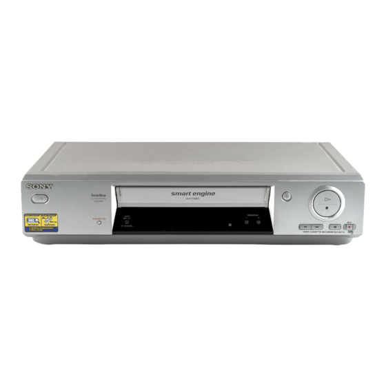
Photo: SLV-SE810
SE710
SE810
SX710
SE710B
SE810B
SX710B
SE710D
SE810D
SX710D
SE710E
SE810E
SX710E
SE710G
SE810G
SX710K
SE710I
SE810K
SX710N
SE710K
SE810N
SE710N
x
ao
u163
y
i
http://www.xiaoyu163.com
2 9
8
Q Q
3
6 7
1 3
1 5
SX717
SX810
X9
SX717D
SX810D
X9B
SX717E
X9D
X9E
X9G
X9N
VIDEO CASSETTE RECORDER
co
.
9 4
2 8
French Model
SLV-SE610B/SE710B/SE810B/
German Model
SLV-SE710D/SE810D/SX710D/
SX717D/SX810D/X9D
Italian Model
East European Model
Russian Model
SLV-SE610K/SE610N/SE710K/SE710N/
SE810K/SE810N/SX710K/SX710N/X9N
North European Model
SLV-SE610E/SE710E/SE810E/
SX710E/SX717E/X9E
UK Model
SLV-SE610G/SE710G/
SE710I/SE810G/X9G
0 5
8
2 9
9 4
2 8
m
9 9
SX710B/X9B
SLV-SE610A
9 9
Advertisement
Table of Contents

Related Manuals for Sony SLV-SX717


Summarization of Contents
Service Manual
French Model Variants
Lists French variants of the VCR models.
German Model Variants
Lists German variants of the VCR models.
Italian Model Variants
Lists Italian variants of the VCR models.
East European Model Variants
Lists East European variants of the VCR models.
Russian Model Variants
Lists Russian variants of the VCR models.
North European Model Variants
Lists North European variants of the VCR models.
UK Model Variants
Lists UK variants of the VCR models.
Mechanism and Hi-Fi Features
Notes on VHS mechanical adjustments.
Model Name Abbreviations
Table of abbreviated model names and their full names.
Specifications and Safety
System Specifications
Details system specifications including channel coverage and RF output.
Tape Speed Specifications
Specifies tape speeds for different modes and systems.
Maximum Recording and Playback Time
Indicates maximum recording and playback duration.
Fast-Forward and Rewind Time
Specifies fast-forward and rewind duration.
Safety Check-Out Procedure
Performs safety checks before releasing the set to the customer.
Safety Component Warnings
Warns about critical safety components requiring specific replacement parts.
Input/Output and General Information
LINE-1 (TV) Connector Details
Details the 21-pin connector for TV input/output.
Decoder and Line Input Connectors
Describes 21-pin connectors for decoder or line inputs.
General Power Requirements
Specifies voltage and frequency requirements.
Power Consumption Details
Details power consumption in various modes.
Operating and Storage Temperatures
Specifies operating and storage temperature ranges.
VCR Dimensions and Mass
Lists physical dimensions and weight of the VCR models.
Supplied Accessories List
Lists items included with the VCR.
Section 2: Disassembly Procedures
2-1. Upper Case Removal
Steps to remove the upper case.
2-3. Power Block (SRV938EK) Removal
Steps to remove the power block.
2-2. Rear Panel Removal
Procedure for removing the rear panel.
2-4. Front Panel Section Removal
Instructions for removing the front panel section.
Section 1: General Information
Getting Started Guide
Guides for initial setup and operation.
Parts and Controls Identification
Identifies and locates VCR parts and controls.
Remote Commander Setup
Unpacking the VCR
Instructions for unpacking the VCR and its accessories.
Setting Up the Remote Commander
Guides for inserting batteries and using the remote.
Connecting and Tuning the VCR
TV Control Buttons and Codes
Explains TV control buttons and lists codes for other TV brands.
Connecting the VCR to a TV
Instructions for connecting the VCR to a TV.
VCR Tuning Procedures
Scart (EURO-AV) Connection Guide
Instructions for connecting via Scart.
SMARTLINK Features Overview
Explains SMARTLINK features and their availability.
Additional Connection Options
Describes connecting to stereo systems or tuners.
Tuning the TV for VCR Signal Reception
Guides on tuning the TV to receive VCR signals.
VCR Setup and Channel Tuning
Tuning TV for Scart and Non-Scart TVs
Tuning steps for TVs with and without Scart connectors.
Auto Set Up Function Guide
Guides for automated VCR setup including language and channels.
Clock and Language Settings
Setting the VCR Clock Manually
Manual procedure for setting the clock and date.
Auto Clock Set Station Change
How to change stations for auto clock setup.
Channel Presetting and Management
Selecting On-Screen Display Language
Procedure to change the on-screen display language.
Manual Channel Presetting
Manual steps to tune and set channels if Auto Set Up fails.
Programme Position Management
Changing Programme Positions
Steps to change the order of preset channels.
Disabling Unwanted Programme Positions
Procedure to disable unused or unwanted channel positions.
Advanced Features and Connections
Changing Station Names
Instructions for assigning custom names to stations.
Canal Plus Decoder Setup
Guides for connecting and setting up a Canal Plus decoder.
Basic VCR Operations
Playing a Tape Guide
Instructions for playing video tapes.
Recording TV Programmes Guide
Guides for recording television programs.
Dial Timer and ShowView Recording
Dial Timer Clock and Stop Procedures
Steps to set clock, return, and stop Dial Timer recording.
Demonstration Mode for Dial Timer
Explanation of the demonstration mode for Dial Timer.
ShowView System Recording Guide
Guide for timer recording using the ShowView system.
Clock and Channel Setup
VCR Clock Setting Procedures
Steps for setting the VCR clock manually or automatically.
On-Screen Display Language Selection
Procedure to change the on-screen display language.
Manual Channel Presetting Steps
Manual steps to tune and set channels.
Programme Position Management
Changing Programme Positions
Steps to change the order of preset channels.
Disabling Unwanted Programme Positions
Procedure to disable unused or unwanted channel positions.
Station Naming and Canal Plus Setup
Changing VCR Station Names
Instructions for assigning custom names to stations.
Canal Plus Decoder Connection
Details on how to connect a decoder.
Setting Canal Plus Channels
Steps to tune Canal Plus channels.
Menu Options and External Connections
Changing VCR Menu Options
How to change various settings via the VCR's menu system.
Connecting to External Audio/Video Equipment
Instructions for connecting external audio/video equipment.
Basic Editing Features
Audio Dubbing Functionality
How to add commentary tracks to tapes.
Disassembly Procedures
Upper Case Removal Steps
Steps to remove the upper case.
Power Block (SRV938EK) Removal
Steps to remove the power block.
Rear Panel Removal Steps
Procedure for removing the rear panel.
Front Panel Section Removal Steps
Instructions for removing the front panel section.
Mechanism and Board Removal
Mechanism Deck Removal Steps
Steps to remove the main mechanism deck.
MA-400 Board Removal Steps
Procedure for removing the MA-400 main board.
Section 3: Block Diagrams
Overall Block Diagram
A comprehensive overview of the VCR's interconnected systems.
Printed Wiring Boards: DS-95 and JK-201
DS-95 Board Layout
Printed wiring board layout for the DS-95.
JK-201 Board Layout
Printed wiring board layout for the JK-201.
Section 5: Interface and IC Pin Functions
System Control-Video Block Interface (IC162)
Explains the interface between system control and the video block.
System Control-Servo Peripheral Interface (IC162)
Describes the interface for servo peripheral circuits.
System Control Interface Descriptions
System Control-Peripheral Circuit Interface (IC162)
Explains the interface for system control peripheral circuits.
System Control-Audio Block Interface (IC162)
Describes the interface for the audio block.
Section 6: Error Codes
Error Code Indication Guide
Provides a table of error codes and their meanings.
Section 7: Adjustments
Mechanical Adjustments Guide
Instructions for physical adjustments.
Electrical Adjustments Procedures
Procedures for electrical adjustments.
Pre-Adjustment Preparations
Lists necessary instruments and connections for adjustments.
Alignment Tapes Required
Lists specific alignment tapes required for adjustments.
Specified I/O Levels and Impedance
Specifies input/output signal levels and impedance.
Video Section Adjustment Setup
Details the setup for video section adjustments.
Electrical Adjustment Sequences
Adjusting Sequence Overview
Outlines the order for performing electrical adjustments.
Power Supply Adjustment Procedures
Steps for adjusting the power supply.
Servo System Adjustment Procedures
Procedures for adjusting the servo system.
Audio System Adjustments
AF Switching Position Adjustment
Adjusts AF switching position for better interchangeability.
Frequency Response Check
Confirms frequency characteristics.
Level and Distortion Factor Checks
Checks record/play levels and distortion.
Signal-to-Noise Ratio Check
Confirms signal-to-noise ratio.
ACE Head Adjustment Procedure
Adjusts the ACE head.
E-E Output Level Check Procedure
Checks the output level against reference.
Normal Audio System Adjustments
Adjustments for normal audio system operation.
Characteristic Checks
Overall Level and Distortion Check
Checks record/play levels and distortion against reference.
Overall Signal-to-Noise Ratio Check
Confirms signal-to-noise ratio within specifications.
ACE Head Adjustment Steps
Adjusts the ACE head.
E-E Output Level Check Steps
Checks the output level against reference input.
Frequency Response Check Steps
Confirms frequency characteristics.
Parts Arrangement for Adjustments
MA-400 Board Component Layout
Component layout for the MA-400 board.
SRV938EK Board Component Layout
Component layout for the SRV938EK board.
Section 8: Repair Parts List
Important Notes on Parts
Important notes regarding parts ordering and identification.
Exploded Views of VCR Components
Diagrams showing disassembled VCR parts.
Front Panel and Cabinet Parts
Lists parts for the front panel and cabinet.
Chassis and Mechanism Assemblies
Chassis Assembly Diagram
Diagram of the VCR chassis assembly.
Mechanism Chassis Assembly (Part 1)
Exploded view of the mechanism chassis assembly.
Need help?
Do you have a question about the SLV-SX717 and is the answer not in the manual?
Questions and answers