
Related Manuals for EUTECH INSTRUMENTS PC 700 - REV 3


Summary of Contents for EUTECH INSTRUMENTS PC 700 - REV 3
- Page 1 Instruction Manual PC 700 pH/mV/Conductivity/ºC/ºF Bench Meter Technology Made Easy ... Part of Thermo Fisher Scientific 68X541704 Rev 3 Nov. 2010...
-
Page 3: Table Of Contents
TABLE OF CONTENTS 1. INTRODUCTION .............. 1 2. GETTING STARTED............2 Keypad Functions ..............2 LCD Annunciators ..............3 Meter Connections ..............3 3. CONDUCTIVITY ELECTRODE ........4 4. PH AND MV CALIBRATION..........4 pH Calibration ................. 4 Millivolt (mV) Offset Adjustment ..........6 5. - Page 4 3.3 AtC (Auto Temp Compensation)—Con & TDS only ..14 3.4 tdS (TDS factor)—Con & TDS only ........14 3.5 t.CO (Temperature Coefficient)—Con & TDS only.... 14 9.10 3.6 t.nr (Normalization Temperature in ºC)—Con & TDS only 15 9.11 3.7 ACAL (Auto Conductivity Calibration)—Con & TDS only .. 15 9.12 3.8 SPC (Single Point Calibration)—Con &...
-
Page 5: Introduction
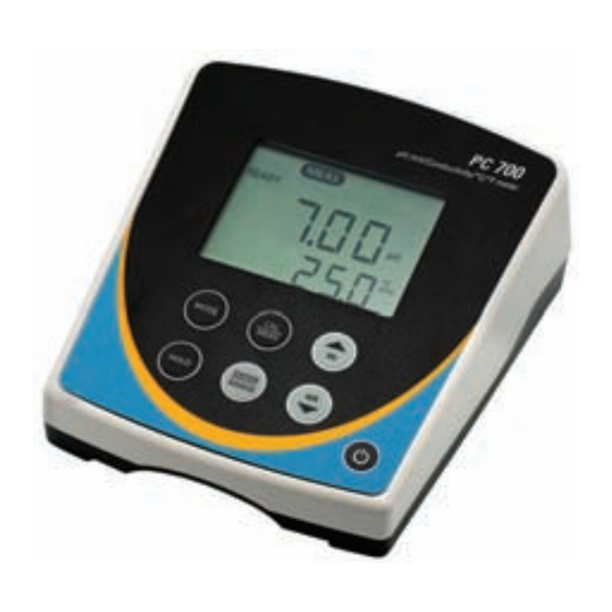
1. INTRODUCTION Thank you for purchasing our PC 700 series benchtop meter. This microprocessor-based meter is economical and simple to use. The design incorporates a large LCD for clear viewing, yet offers a small footprint to conserve space. The PC 700 measures pH, mV (ORP), conductivity, or TDS simultaneously with temperature (ºC or ºF). -
Page 6: Getting Started
2. GETTING STARTED 2.1 Keypad Functions Powers the meter on and off. Upon power on, the meter automatically begins in the mode that was last used. Calibration and memory values are retained even if meter is unplugged. Toggle between available measurement modes— pH/Temp, mV/Temp, Conductivity/Temp, or TDS/Temp. -
Page 7: Lcd Annunciators
2.2 LCD Annunciators 2.3 Meter Connections Power supply CON/ 8-pin DIN connection for 2-cell Con/TDS/Temp electrode TEMP BNC connection for pH, or ORP (Redox) electrode... -
Page 8: Conductivity Electrode
3. CONDUCTIVITY ELECTRODE The PC 700 includes an electrode with a nominal cell constant of k = 1.0, built-in temperature sensor, and 1 meter cable. The Ultem body housing has good chemical resistant properties. The electrode design offers fast temperature response and reduces air entrapment, ensuring accurate, repeatable, and stable readings. - Page 9 The following calibration standards are automatically recognized; USA buffer group 1.68, 4.01, 7.00, 10.01, 12.45 NIST buffer group 1.68, 4.01, 6.86, 9.18, 12.45 See Section 9.6 to change the buffer group 1) Press as needed to select pH. 2) Dip the pH and ATC electrodes into pH buffer and press .
-
Page 10: Millivolt (Mv) Offset Adjustment
4.2 Millivolt (mV) Offset Adjustment Oxidization Reduction Potential (ORP or Redox) is not a precise measurement, but is useful as a relative indicator. As such, mV offset adjustment is not meant to enhance accuracy, but rather to make readings comparable to a reference. Commercial ORP solutions are often used as a check standard in which a meter/electrode system are verified to be close to a given value, instead of being used as a calibration standard in which adjustments are made in an attempt to... -
Page 11: Single Or Multi-Point Calibration
If you only use calibration standards that are listed in TABLE 1, automatic calibration is recommended. If you intend to calibrate with one or more standards that are not listed in TABLE 1, the PC 700 must be set for manual calibration instead. The factory default is automatic conductivity calibration. -
Page 12: General Calibration Tips
Use Multi-Point Calibration for individual calibration in each range. This will restrict an individual calibration so that it is applied to one range only. When using multi-point calibration, perform a calibration in each range that you expect to use for best results. The factory default is Single-Point Calibration. -
Page 13: Manual Conductivity & Tds Calibration Procedure
When the READY indicator appears, press to accept. The primary reading will flash briefly before returning to measurement mode upon successful calibration. 5.5 Manual Conductivity & TDS Calibration Procedure Press as needed to select conductivity (μS or mS) or TDS (ppm or ppt) calibration. -
Page 14: Conductivity And Tds Measurement
6. CONDUCTIVITY AND TDS MEASUREMENT 6.1 Taking Measurements Rinse the electrode with de-ionized or distilled water before use to remove any impurities. Gently shake excess water droplets. Dip the probe into the sample beyond the upper steel band (utilize the fill line on the outside of the probe guard for reference). -
Page 15: Hold Function
7. HOLD FUNCTION For prolonged observation of a reading, press during measurement mode to freeze the display. The “HOLD” indicator will display when the reading is held. To release the held value and resume measurement, press again or insert the held value into memory by pressing 8. -
Page 16: Setup Functions
9. SETUP FUNCTIONS Use the setup feature to customize your instrument operation. First, select the appropriate measurement mode you wish to adjust by pressing until the desired units are displayed (i.e. pH, mV, Conductivity, or TDS). During measurement, press and hold for 5 seconds to enter SETUP mode of the parameter being measured. -
Page 17: Conf (Configuration)
be available to view. If no calibration is stored, the offset will be 0.0 mV and the slope is 100%. 9.3 3.0 ConF (Configuration) Press to access set-up programs 3.1 thru 3.9. 9.4 3.1 rdY (Ready / Stability Indicator) Press Press to choose READY “On”, READY “OFF”, or Auto HOLd. -
Page 18: Atc (Auto Temp Compensation)-Con & Tds Only
9.7 3.3 AtC (Auto Temp Compensation)—Con & TDS only Press Press to select “Yes” or “No”. Press to confirm. 9.8 3.4 tdS (TDS factor)—Con & TDS only Press Press to select the desired TDS factor (.40 to 1.00). Press to confirm. 9.9 3.5 t.CO (Temperature Coefficient)—Con &... -
Page 19: T.nr (Normalization Temperature In ºc)-Con & Tds Only
9.10 3.6 t.nr (Normalization Temperature in ºC)—Con & TDS only When Automatic Temperature Compensation is used, measurements are adjusted by the temperature coefficient to the normalization temperature. The default value is 25 ºC. Press Press to select the desired value (15.0 to 30.0). Press to confirm. -
Page 20: Rst (Reset)
k = 1.0 ideal for mid-range measurements k = 10 ideal for high measurements >20 mS (>10 ppt). Press Press to select 0.1, 1.0, or 10.0 Press to confirm. 9.14 4.0 rSt (Reset) Press Press to select “Yes” (Reset) or “No” (Cancel). If “Yes”, press to select “Cal”... -
Page 21: Calculating Tds Conversion Factor
10. CALCULATING TDS CONVERSION FACTOR You can calibrate TDS using the value of the calibration standard solution at a standard temperature such as 25 ºC. To determine the conductivity- to-TDS conversion factor use the following formula: Factor = Actual TDS ÷ Actual Conductivity @ 25 ºC •... -
Page 22: Calculating Temperature Coefficients
11. CALCULATING TEMPERATURE COEFFICIENTS To determine the temperature coefficient of your sample solution use this formula: Where: tc = Temperature coefficient 25 = 25 ºC = Conductivity at Temp 1 = Conductivity at Temp 2 T1 = Temp 1 T2 = Temp 2 NOTE: A controlled temperature water bath is ideal for this procedure. -
Page 23: Replacements And Accessories
12. REPLACEMENTS AND ACCESSORIES Part number Ordering Code Item Description Eutech Oakton Instruments Instruments PC 700 with pH electrode (ECFC7252101B / 59001- ECPC70043S 70), conductivity/temp electrode (CONSEN9501D / 35413-00 01X543601 35608-74), integral stand,100/240 VAC PC 700 with integral stand, 100/240 VAC 35413-20 Plastic, Gel-filled, Double-junction pH electrode ECFC7252201B... -
Page 24: Troubleshooting Guide
13. TROUBLESHOOTING GUIDE PROBLEM CAUSE SOLUTION No display Main power not switched on. Switch on the power supply. AC Adapter socket not inserted Re-insert AC Adapter. properly. “Ur” (Under Measured value is out Check electrode is connected. range) of range. Clean or replace electrode. - Page 25 PROBLEM CAUSE SOLUTION Calibration error. Use fresh buffer solutions. Buffer value does not match Check electrode connection. displayed value or electrode is Clean & recondition electrode. disconnected or failing. Replace electrode. Unstable pH Broken or worn electrode Replace electrode reading External ‘noises’...
-
Page 26: Specifications
14. SPECIFICATIONS pH Range -2.00 to 16.00 pH Resolution 0.01 pH ± 0.01 pH Accuracy Calibration Points Up to 5 points with Auto-buffer recognition USA : pH 1.68, 4.01, 7.00, 10.01,12.45 Buffer Options NIST: pH 1.68, 4.01, 6.86, 9.18 ,12.45 Slope Display Yes (with offset) ±... - Page 27 Normalization 15.0 to 30.0 ºC (adjustable) Cell Constant 0.1, 1.0, 10.0 (selectable) TDS Factor 0.40 to 1.00 (adjustable) Automatic (4 points); Maximum 1 per range Calibration points Manual (5 points); Maximum 1 per range Auto-ranging Hold Function Memory 100 data sets Input BNC, 8-pin DIN Power...
-
Page 28: Warranty
If repair or adjustment is necessary and has not been the result of abuse or misuse within the designated period, please return – freight prepaid – and correction will be made without charge. Eutech Instruments/Oakton Instruments will determine if the product problem is due to deviations or customer misuse. -
Page 29: Return Of Items
For your protection, items must be carefully packed to prevent damage in shipment and insured against possible damage or loss. Eutech Instruments will not be responsible for damage resulting from careless or insufficient packing. A restocking charge will be made on all unauthorized returns. - Page 30 NOTES...
- Page 32 For more information on our products, please contact our channel partner or visit our websites listed below: Oakton Instruments Eutech Instruments Pte Ltd 625 E Bunker Court Blk 55, Ayer Rajah Crescent, Vernon Hills, IL 60061 #04-16/24 Singapore 139949 Tel: (1) 888-462-5866...
Need help?
Do you have a question about the PC 700 - REV 3 and is the answer not in the manual?
Questions and answers