Advertisement
Quick Links
WARNING/CAUTION/NOTE
Please read this manual and follow its instructions carefully. To emphasize special information, the words
,
WARNING
CAUTION
!
!
lighted by these signal words.
WARNING
!
Indicates a potential hazard that could result in death or injury.
CAUTION
!
Indicates a potential hazard that could result in vehicle damage.
NOTE:
Indicates special information to make maintenance easier or instructions clearer.
WARNING
!
This service manual is intended for authorized Suzuki dealers and qualified service technicians only.
Inexperienced technicians or technicians without the proper tools and equipment may not be able to
properly perform the services described in this manual.
Improper repair may result in injury to the technician and may render the vehicle unsafe for the driver
and passengers.
WARNING
!
For vehicles equipped with a Supplemental Restraint (Air Bag) System:
• Service on and around the air bag system components or wiring must be performed only by an
authorized SUZUKI dealer. Refer to "Air Bag System Components and Wiring Location View" under
"General Description" in air bag system section in order to confirm whether you are performing ser-
vice on or near the air bag system components or wiring. Please observe all WARNINGS and "Ser-
vice Precautions" under "On-Vehicle Service" in air bag system section before performing service
on or around the air bag system components or wiring. Failure to follow WARNINGS could result in
unintentional activation of the system or could render the system inoperative. Either of these two
conditions may result in severe injury.
• If the air bag system and another vehicle system both need repair, Suzuki recommends that the air
bag system be repaired first, to help avoid unintended air bag system activation.
• Do not modify the steering wheel, instrument panel or any other air bag system component on or
around air bag system components or wiring. Modifications can adversely affect air bag system
performance and lead to injury.
• If the vehicle will be exposed to temperatures over 93 °C (200 °F), for example, during a paint baking
process, remove the air bag system components, that is air bag (inflator) modules, SDM and/or seat
belt with pretensioner, beforehand to avoid component damage or unintended activation.
The circle with a slash in this manual means "Don't do this" or "Don't let this happen".
IMPORTANT
and NOTE have special meanings. Pay special attention to the messages high-
Advertisement

Related Manuals for Suzuki M13


Summarization of Contents
General Information and Safety
Warning, Caution, and Note Signal Words
Defines the meaning of signal words like WARNING, CAUTION, and NOTE used in the manual.
Service Manual Usage and Safety Precautions
Highlights risks of improper repairs by unqualified technicians and manual usage.
Air Bag System Safety Precautions
Critical safety warnings for Supplemental Restraint Systems.
Genuine Suzuki Parts and Accessories Recommendation
Recommends genuine parts for performance and safety.
Engine Oil Pressure Measurement
Oil Pressure Specification and Procedure
Details engine oil pressure specs and measurement steps.
Engine Valve Lash Adjustment
Valve Lash Measurement and Tappet Replacement
Guides on measuring valve lash and replacing tappets.
Air Cleaner System Maintenance
Air Cleaner Filter Service
Instructions for filter removal, installation, inspection, and cleaning.
Air Cleaner Assembly Removal and Installation
Procedure for removing and installing the entire air cleaner assembly.
Intercooler System Maintenance
Intercooler Components Overview
Diagram and list of intercooler system parts.
Intercooler Removal and Installation
Step-by-step guide for intercooler removal and installation.
Cylinder Head Cover Service
Cylinder Head Cover Components and Gasket
Diagram and list of parts for the cylinder head cover.
Cylinder Head Cover Removal and Installation
Procedure for removing and installing the cylinder head cover.
Engine Component Service
Oil Pressure Switch Removal and Installation
Instructions for removing and installing the oil pressure switch.
Heat Exchanger Removal and Installation
Procedure for removing and installing the heat exchanger.
EGR Valve and Intake Pipe System Service
EGR Valve and Intake Pipe Components
Diagram and list of EGR valve and intake pipe parts.
EGR Valve and Intake Pipe Removal and Installation
Procedure for removing and installing the EGR valve and intake pipe.
Turbocharger System Service
Turbocharger Components
Diagram and list of turbocharger system parts.
Turbocharger Removal and Installation
Detailed steps for turbocharger assembly removal and installation.
Turbocharger Inspection
Procedure for inspecting the turbocharger's rotating parts.
Exhaust Manifold Service
Exhaust Manifold Components
Diagram and list of exhaust manifold parts.
Exhaust Manifold Removal and Installation
Procedure for removing and installing the exhaust manifold.
Oil Pan and Oil Pump Strainer Service
Oil Pan and Oil Pump Strainer Components
Diagram and list of oil pan and oil pump strainer parts.
Oil Pan and Oil Pump Strainer Removal and Installation
Procedure for removing and installing the oil pan and oil pump strainer.
Engine Assembly Service
Engine Assembly Removal Procedure
Detailed steps for removing the engine assembly from the vehicle.
Engine Assembly Installation Procedure
Steps for installing the engine assembly back into the vehicle.
Timing Belt and Tensioner System Service
Timing Belt and Belt Tensioner Components
Diagram and list of timing belt and tensioner parts.
Timing Belt and Belt Tensioner Removal and Installation
Procedure for removing and installing the timing belt and tensioner.
Oil Pump and Chain System Service
Oil Pump and Oil Pump Chain Components
Diagram and list of oil pump and chain parts.
Oil Pump and Oil Pump Chain Removal and Installation
Procedure for removing and installing the oil pump and chain.
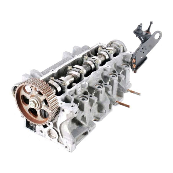
Camshaft and Tappet System Service
Camshaft and Tappet Components
Diagram and list of camshaft and tappet parts.
Camshaft and Tappet Removal and Installation
Procedure for removing and installing camshaft and tappets.
Camshaft and Tappet Inspection
Inspection methods for camshaft wear, journal wear, and clearance.
Power Door Lock and Keyless Entry System
Keyless Entry System Component Location
Diagram showing the location of keyless entry system components.
Keyless Entry System Operation and Inspection
Details system description, signal modes, and operational checks.
Keyless Entry System Circuit Check
Checks for voltage and continuity in keyless entry circuits.
Transmitter Battery Replacement
Transmitter Battery Replacement Procedure (M13 Engine)
Steps to replace the transmitter battery for the M13 engine.
Transmitter Battery Replacement Procedure (K9K Engine)
Steps to replace the transmitter battery for the K9K engine.
Key Code Registration Procedure
Code Registration for M13 Engine Model
Procedure for registering key codes for M13 engine model transmitters.
Code Registration for K9K Engine Model
Procedure for registering key codes for K9K engine model transmitters.
Power Door Mirror System Service
Door Mirror Actuator Inspection
Procedure for inspecting door mirror actuator operation with battery voltage.
Door Mirror Heater System Inspection
Mirror Heater Inspection
Procedure for checking continuity of the door mirror heater element.
Need help?
Do you have a question about the M13 and is the answer not in the manual?
Questions and answers