Table of Contents
Advertisement
QQ
3 7 63 1515 0
SERVICE MANUAL
•
HCD-D390/D790/G5500/XB33/XB44/
XB50/XB60 is the tuner, deck, CD and
amplifier section in LBT-D390/D790/G5500/
XB33/XB44/XB50/XB60
* Dolby noise reduction manufactured under license
from Dolby Laboratories Licensing Corporation.
"DOLBY" and the double-D symbol a are
trademarks of the Dolby Laboratories Licensing
Corporation.
TE
L 13942296513
For the U.S. model
AUDIO POWER SPECIFICATIONS
POWER OUTPUT AND TOTAL HARMONIC DISTORTION:
With 8 ohm loads, both channels driven, from 70-20,000 Hz; rated 100
watts per channel minimum RMS power, with no more than 0.9 % total
harmonic distortion from 250 milliwatts to rated output.
Amplifier section
(HCD-D390/D790/G5500)
Continuous RMS power output:
Total harmonics distortionm:
(HCD-XB50)
DIN power output (Rated):80 + 80 watts (8 ohms at 1 kHz, DIN)
Continuous RMS power output (Reference):
Music power output (Reference):
(HCD-XB60)
DIN power output (Rated):
www
Continuous RMS power output (Reference):
Music power output (Reference):
.
MICROFILM
http://www.xiaoyu163.com
.
120 + 120 watts (8 ohms at 1 kHz, 10% THD)
Less than 0.07% (8 ohms at 1 kHz, 50 W)
100 + 100 watts (8 ohms at 1 kHz, 10% THD)
170 + 170 watts (8 ohms at 1 kHz, 10% THD)
100 + 100 watts (8 ohms at 1 kHz, DIN)
120 + 120 watts (8 ohms at 1 kHz, 10% THD)
x
ao
u163
y
210 + 210 watts (8 ohms at 1 kHz, 10% THD)
i
http://www.xiaoyu163.com
HCD-D390/D790/G5500/
XB33/XB44/XB50/XB60
2 9
8
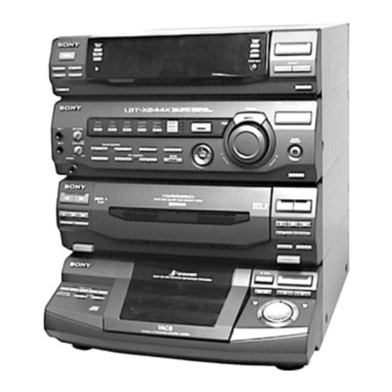
Photo: HCD-XB44
Model Name Using Similar Mechanism
CD
CD Mechanism Type
Section
Base Unit Name
Optical Pick-up Name
Q Q
Model Name Using Similar Mechanism
3
6 7
1 3
1 5
Tape Deck
Section
Tape Transport Mechanism Type
SPECIFICATIONS
(HCD-XB33)
The following measured at AC 120/240 V, 50 Hz
DIN power output (Rated):
Continuous RMS power output (Reference):
Peak music power potput (Reference):
(HCD-XB44)
The following measured at AC 120/240 V, 50 Hz
DIN power output (Rated):
Continuous RMS power output (Reference):
Peak music power output (Reference):
COMPACT DISC DECK RECEIVER
co
.
9 4
2 8
US Model
HCD-D390/D790/G5500
Canadian Model
HCD-390/D790
AEP Model
UK Model
HCD-XB50/XB60
E Model
Australian Model
HCD-XB33/XB44
HCD-D290/
G3300/XB3
CDM37L-5BD29AL
BU-5BD29AL
KSS-213D/Q-NP
HCD-D290/
0 5
8
2 9
9 4
2 8
G3300/XB3
TCM-220WR2
100 + 100 watts (6 ohms at 1 kHz, DIN)
120 + 120 watts
(6 ohms at 1 kHz, 10% THD)
1,500 watts
120 + 120 watts (6 ohms at 1 kHz, DIN)
140 + 140 watts
(6 ohms at 1 kHz, 10% THD)
2,000 watts
— Continued on next page —
m
9 9
9 9
Advertisement
Table of Contents

Related Manuals for Sony HCD-XB60


Summarization of Contents
Specifications
Audio Power Specifications
Details power output and total harmonic distortion for audio amplifier section.
Component Specifications
CD Player Specifications
Details specifications for the CD player, including laser, wavelength, frequency response, etc.
Tape Player Specifications
Details specifications for the tape deck, including recording system and frequency response.
Tuner Specifications
Details specifications for FM and AM tuner sections, including tuning range and intermediate frequency.
General Specifications
Covers power requirements, power consumption, dimensions, and mass.
Safety Information
General Cautions
Warns about potential hazards from controls, adjustments, and chip component replacement.
Safety Check-out Procedures
Outlines post-service safety checks, including AC leakage testing.
Safety-Related Component Warnings
Highlights critical components for safe operation that require specific replacement parts.
Servicing Notes
Handling Optical Pick-up Block
Provides precautions for handling the optical pick-up block and flexible boards.
Laser Diode Emission Check
Details precautions for checking laser diode emission to avoid exposure.
Disassembly
Upper Case Disassembly
Details the procedure for removing the upper case using screws.
Front Panel Section Disassembly
Describes how to detach the front panel section and its connections.
Main Board Disassembly
Explains how to remove the main board, including power cord and connectors.
Main Section Disassembly
Details the procedure for removing the main section from the chassis.
Test Modes
CD Section Test Modes
Covers MC Cold Reset, CD Delivery, MC Hot Reset, and Sled Servo modes for CD section testing.
Indicator and Key Check Test Mode
Lights all LEDs and tubes, enabling key check mode for button functionality.
AM Tuner Step Changeover
Allows switching AM channel steps between 9kHz and 10kHz.
Aging Mode Operation
Covers CD and Tape Deck sections, including operation methods, sequences, and deck selection.
Mechanical Adjustments
Mechanical Adjustments Precautions
Lists general precautions before performing mechanical adjustments, including cleaning and tool usage.
Torque Measurements
Details the modes, torque meter, and meter readings for torque measurements.
Tape Tension Measurements
Specifies the tension meter and meter readings for tape tension measurements.
Electrical Adjustments
Deck Section Adjustments
Covers general precautions and settings for deck section electrical adjustments.
Deck A Tape Speed Adjustment
Details the procedure for adjusting tape speed for Deck A using a frequency counter.
Playback Level Adjustment (Deck A & B)
Explains the procedure for adjusting playback levels for both decks using a level meter.
Tuner Section Adjustments
AM Tuned Level Adjustment
Explains the procedure for adjusting AM tuned level using an RF SSG and TUNED indicator.
FM Tuned Level Adjustment
Details the procedure for adjusting FM tuned level using an RF SSG and TUNED indicator.
FM Polar Adjustment (East European/CIS)
Describes the procedure for FM polar adjustment using RF SSG and level meter.
CD Section Adjustments
CD Focus Bias Check
Details the procedure for checking focus bias, including waveform observation.
CD RF Level Check
Explains how to check the RF signal level and waveform clarity.
CD E-F Balance and Track Jump Check
Describes the procedure for checking E-F balance and track jump using an oscilloscope.
Diagrams
Circuit Board Locations
Shows the physical layout and connections of various circuit boards within the unit.
Block Diagrams - CD Section
Provides a block diagram illustrating the signal flow and components in the CD section.
Tuner Section Diagram (AEP, UK Model)
Shows the schematic diagram for the tuner section specific to AEP and UK models.
Printed Wiring Board - BD Section
Shows the component layout for the BD section printed wiring board.
IC Block Diagrams
IC Block Diagrams - BD Section
Illustrates block diagrams for ICs within the BD section, showing internal functions and connections.
IC Block Diagrams - Tuner Section
Shows block diagrams for ICs within the tuner section, detailing their roles in signal processing.
IC Pin Function Description
IC Pin Functions - Main Board IC301 (Main Control)
Details the pin functions for IC301, the main control unit on the main board.
IC Pin Functions - Panel Board IC601 (Display Control)
Lists the pin functions for IC601, responsible for display control on the panel board.
Exploded Views
Exploded View - Case and Rear Panel
Shows an exploded view of the unit's case and rear panel, identifying parts and their assembly.
Exploded View - Front Panel Section (1)
Provides an exploded view of the front panel section, detailing parts like buttons, indicators, and panels.
Exploded View - Front Panel Section (2)
Continues the exploded view of the front panel section, showing more parts like knobs and indicator assemblies.
Electrical Parts List
Audio Section Electrical Parts List
Lists all electrical components used in the audio board, including capacitors, resistors, ICs, and connectors.
BD Section Electrical Parts List
Lists electrical components for the BD section, including resistors, transistors, and capacitors.
BD LED and CD Motor Electrical Parts List
Lists components for the BD LED and CD motor sections, including resistors, switches, diodes, and ICs.
TC-B Switch Section Parts List
Lists components for the TC-B switch board, including diodes, resistors, switches, and capacitors.
Need help?
Do you have a question about the HCD-XB60 and is the answer not in the manual?
Questions and answers