Table of Contents
Advertisement
Advertisement
Chapters
Table of Contents

Related Manuals for Bose Entero 4100


Summarization of Contents
Getting Started
Unpacking
Inspect the amplifier upon unpacking and save original packing materials for potential returns.
Installation
Mount amplifiers in standard 19-inch racks using metric M6 bolts for secure installation.
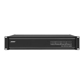
Panel Front View
Illustrates the front panel of different Bose Entero amplifier models.
Power Switching / Remote On/Off-Switching
Local Switching
Uses the rear panel power switch for direct on/off control, disabling remote options.
Remote Switching with 12 VDC-Control Voltage
Utilizes PHOENIX terminal for remote on/off control using a 12 VDC signal for sequential switching.
Front Indicators and Control
LED Indicators
Explains the function of various LEDs (POWER, CLIP, SIGNAL, PROTECT, MODE) on the amplifier's front panel.
Audio Input Connections
Entero 440/840
Details PHOENIX input connectors for channels 1-4 and 5-8 on Entero 440 and 840 models.
Entero 4100/4200/4400
Describes combined XLR/TRS input connectors for the Entero 4100, 4200, 4400 models.
Loudspeaker Output Connections
Output wiring
Guidance on using heavy gauge wire for speaker connections to minimize power loss and improve damping.
Output Connectors
Details connecting loudspeaker cables to PHOENIX output connectors and polarity labeling.
100 Volt Systems
Information on connecting speaker outputs to transformer packages (Trapack 2 or Trapack 4) for 100V applications.
Operation Modes
Stereo Operation
Describes independent channel operation where input 1 drives output 1, and so on.
Parallel Operation
Explains how to feed both inputs of a channel pair with the same signal for parallel operation.
Bridged Operation
Details how to use channels in BRIDGE mode, specifying input signal wiring and load impedance.
Need help?
Do you have a question about the Entero 4100 and is the answer not in the manual?
Questions and answers