Table of Contents
Advertisement
SUPPLEMENT
Q4, part number 102428 and Q5, part number 102429 are no longer available with the lead length
needed for soldering to the PCB. Use the part numbers listed below when ordering these transis-
tors. Make a note in your Model 1801/1800 power amplifier service manual, part number 192527.
Reference
Designator
Q4
Q5
NOTE: The part numbers listed are kits. They include the following parts:
1. Q4 kit: 1 102428 transistor
3 264371 extension pins
1 192527-S1 supplement.
2. Q5 kit: 1 102429 transistor
3 264371 extension pins
1 192527-S1 supplement.
©
2001 Bose Corporation
10/2001
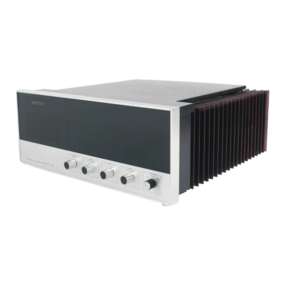
®
Bose
Model 1801/1800
Power Amplifier
Description
SIM, 2N2219
SIM, 2N5415
Part
Note
Number
102428-1K
1
102429-1K
2
Supplement
Part Number 192527-S1
Advertisement
Table of Contents


Need help?
Do you have a question about the 1801 and is the answer not in the manual?
Questions and answers