Advertisement
CD/VIDEO-CD/DVD PLAYER
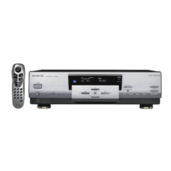
DV-203/2070
QQ
3 7 63 1515 0
DVF-5010/9010/K7010
SERVICE MANUAL
Knob(BUTTON)
(K27-2300-04)
POWER
ON
OFF
PHONES LEVEL
MIN
MAX
PHONES
Phone jack
(E11-0190-05)
TE
L 13942296513
Phono jack
(E63-1059-05)
www
In compliance with Federal Regulations, following are reproduc-
tions of labels on, or inside the product relating to laser product
safety.
.
KENWOOD-Crop. certifies this equipment conforms to DHHS
Regulations No. 21 DFR 1040. 10, Chapter 1, Subchapter J.
DANGER : Laser radiation when open and interlock defeated.
AVOID DIRECT EXPOSURE TO BEAM
Knob
Escutcheon
(K29-7431-04)
(B07-2420-12)
Oscillating module
Phono jack
(W02-1114-05)
(E63-1060-05)
MIX LINE
DIGITAL OUTPUT
6CH. OUTPUT
(PCM/BIT STREAM)
OUTPUT
CENTER
L
L
R
R
COAXIAL
OPTICAL
FRONT SURROUND SUBWOOFER
Phono jack
(E63-0175-05)
Phono jack
(E63-1063-05)
x
ao
y
i
8
Front glass *
(B10-)
VIRTUAL
SURROUND
96 kfs
DTS
ENTER
1
¡
Dressing panel
Knob
(K29-7358-04)
(A21-3693-13)
Q Q
3
6 7
1 3
Metallic cabinet
(A01-3625-01)
VIDEO OUTPUT
COMPONENT VIDEO OUTPUT
1
S-VIDEO 1
S-VIDEO 2
Y
Cb
Cr
2
Phono jack
(E63-1061-05)
Cylindrical receptacle
Phono jack
(E56-0021-05)x2
(E63-1057-05)
Caution : No connection of ground line if disassemble the
unit. Please connect the ground line on rear
u163
panel, PCBs, Chassis and some others.
.
NOTE : Please replace the mechanism PCB
(W02-266x-05) with new one, if it is
malfunction.
2 9
9 4
2 8
© 1998-8/B51-5456-00 (K/K) 3486
Knob
(K29-7355-04)x5
OPEN/CLOSE
PANEL UP / DOWN
ON SCREEN
RETURN
DVD MENU
4
Knob
(K29-7356-03)
1 5
0 5
8
2 9
9 4
Power cord bushing
(J42-0083-05)
AC power cord*
(E30-)
Illust. is DVF-9010.
* Refer to parts list on page 52.
m
co
9 9
3
7
¢
Sub panel
(A22-1809-01)
2 8
9 9
Advertisement
Table of Contents

Related Manuals for Kenwood DVF-5010


Summarization of Contents
Product Overview and Safety
Panel Components and Safety Warnings
Identifies panel components and highlights critical laser safety warnings.
Cautions and Accessories
Handling and Reset Procedures
Covers important cautions for unit handling, condensation, and microprocessor reset.
Included Accessories
Lists accessories supplied with the product, like cables and adapters.
Unit Controls and Indicators
Main Unit Controls (DVF-5010/K7010/9010)
Details front panel controls and indicators for the DVF-5010, DVF-K7010, and DVF-9010 models.
Standby Mode Explanation
Describes the function and status of the unit's standby mode.
Rear Panel Connections
Model-Specific Rear Panel Layouts
Illustrates rear panel connectors for DV-203, DV-2070, DVF-5010, DVF-K7010, and DVF-9010 models.
Remote Control Operation
Remote Control Unit Functions
Explains the layout, buttons, and mode switch functions of the remote controls.
Disassembly Procedures
Mechanism Access and Removal Steps
Step-by-step guide for opening the unit and removing mechanism components like the door panel.
Mechanism Disassembly Details
Disc Ejection and Tray Disassembly
Procedures for troubleshooting disc ejection and disassembling the loading tray.
Mechanism Assembly Procedures
Traverse Unit and Loading Mechanism Assembly
Guidance on reassembling the traverse unit and loading mechanism parts.
Component Replacement Preparation
Loading Tray and Clamper Assembly Steps
Detailed steps for assembling the loading tray and mounting the clamper plate.
PCB Replacement Preparation
Essential preparation steps before replacing electronic components on PCBs.
Final Assembly and Adjustment
Laser Pickup and Disc Motor Assembly
Instructions for assembling the laser pickup and disc motor units.
Mechanism Adjustment Guidelines
Guidance on final assembly and critical adjustments like tangential and tilt.
System Block Diagram
Main System Block Diagrams
High-level block diagrams of the DVD circuit, processor, electric, and display units.
Audio Circuit Description
Model-Specific Audio Circuit Details
Circuit descriptions for the audio output stages across different player models.
Microprocessor Circuit Description
Main Microprocessor Block Diagram and Pins
Block diagram and pin assignments for the main microprocessor in various models.
Microprocessor Pin Details
Microprocessor Pin Function Descriptions
Detailed descriptions of microprocessor pins related to controls, indicators, and signals.
Microprocessor Port Table
Pin Descriptions and Model Port Usage
Detailed pin descriptions and a summary table of port usage across different models.
Microprocessor Port Table Continuation
Further Pin Descriptions and Port Usage
Continues pin descriptions and port usage tables for microprocessor functions.
Operating Voltages and Setup Items
Voltage Matrix and MIC Port Specs
Details voltage levels, MIC port characteristics, and initial setup parameters.
DAC AD1855 Circuit Description
AD1855 Pin Description and Data Modes
Detailed pinout for AD1855 DAC and explanation of its serial data input modes.
DSP/DRIVE.II KAN06 Circuit Description
KAN06 Pin Description and Block Diagram
Pinout and block diagram for the KAN06 DSP/DRIVE.II IC.
DAC PCM1716E Circuit Description
PCM1716E Pin Description and Block Diagram
Pinout and block diagram for the PCM1716E DAC IC.
Test Mode Operations
Test Mode Entry and Key Control Mapping
Guide to entering test mode and table of key functions available within test mode.
NIAGARA Display Test
NIAGARA Display Test Patterns
Visual representation of the NIAGARA display test patterns.
Mechanism Adjustment
Tangential and Tilt Adjustment Procedures
Steps for adjusting tangential tracking and tilt using test equipment.
Main C.B.A. Component Layout
Diagram showing component placement on the Main C.B.A. for adjustment reference.
Video Output Adjustment
NTSC/PAL Video Output Adjustment
Procedures for adjusting video output levels using NTSC/PAL color bars and oscilloscope.
Color Bar Oscilloscope Patterns
Visual references for oscilloscope patterns during video output adjustment.
Wiring Diagrams
Model-Specific Wiring Diagrams
Wiring diagrams illustrating connections for various player models and power supply.
Component Identification
Capacitor and Resistor Descriptions
Explains capacitor/resistor types, codes, dimensions, and ratings.
Processor Unit PCB Layout
Processor Unit Component View
Top-down view of the processor unit PCB showing component placement.
Display Unit PCB Layouts
Display Unit Component Views
Component layout diagrams for various display unit PCBs.
Control Unit PCB Layout
Control Unit Component View
Component placement diagram for the control unit PCB.
Display Unit PCB Layouts (Continued)
More Display Unit Component Views
Component layout diagrams for additional display unit PCB variations.
Main Board PCB Layout
Main Board Component View
Component placement diagram for the main printed circuit board.
Mechanism and Electric Unit PCB Layouts
Mechanism, Main CBA, and Electric Unit PCB Layouts
Component layout diagrams for mechanism, Main CBA, and electric unit PCBs.
Exploded View - Mechanism Part 1
Mechanism Part 1 Assembly Diagram
Exploded view illustrating the assembly of the first part of the mechanism.
Exploded View - Mechanism Part 2
Mechanism Part 2 Assembly Diagram
Exploded view detailing the assembly of the second part of the mechanism.
Exploded View - Unit Components
Unit Components Assembly Diagram
Exploded view showing the assembly of the main unit components.
Parts List - Chassis and Basic Components
DV-2070/DVF-9010 Cabinet, Panel, and Parts
Lists cabinet, panel, and basic external parts for DV-2070/DVF-9010 models.
Parts List - Unit Components
DV-203/DVF-5010/DVF-K7010 Cabinet, Panel, Display Parts
Lists cabinet, panel, and display related parts for DV-203/DVF-5010/DVF-K7010 models.
Parts List - Resistors and ICs
Resistor, IC, and Semiconductor Part Listings
Lists various resistors, ICs, transistors, and diodes with part numbers.
Parts List - Capacitors (Part 1)
Capacitor Part Numbers (C1-C35)
Lists capacitor part numbers, types, and values.
Parts List - Capacitors (Part 2)
Capacitor Part Numbers (C36-C72)
Continues the list of capacitors with their respective part numbers and specifications.
Parts List - Capacitors (Part 3)
Capacitor Part Numbers (C510-C546)
Lists further capacitor part numbers, types, and values.
Parts List - Capacitors (Part 4)
Capacitor Part Numbers (C548-C612)
Completes the capacitor listing with part numbers and specifications.
Parts List - Resistors (Part 1)
Resistor Part Numbers (R1-R38)
Lists resistor part numbers, types, and values.
Parts List - Resistors (Part 2)
Resistor Part Numbers (R39-R77)
Continues the resistor listing with part numbers and specifications.
Parts List - Resistors (Part 3)
Resistor Part Numbers (R80-R516)
Lists further resistor part numbers, types, and values.
Parts List - Resistors (Part 4)
Resistor Part Numbers (R518-R611)
Continues the resistor listing with part numbers and specifications.
Parts List - Resistors (Part 5)
Resistor Part Numbers (R612-R640)
Lists final resistor part numbers, types, and values.
Parts List - Semiconductors (Part 1)
Semiconductor Part Numbers (ICs, Transistors, Diodes)
Lists ICs, transistors, and diodes with part numbers and designations.
Parts List - Semiconductors (Part 2)
Semiconductor Part Numbers (Continued)
Continues the listing of ICs, transistors, and diodes.
Parts List - Model and Destination Codes
Model and Destination Code Explanation
Explains how model and destination codes are used in the parts list.
Specifications - DV-203
DV-203 Technical Specifications
Details the technical specifications for the DV-203 model, including audio, video, and general features.
Specifications - DV-2070/DVF-9010
DV-2070 Specifications
Lists technical specifications for the DV-2070 model.
DVF-9010 Specifications
Details technical specifications for the DVF-9010 model.
Specifications - DVF-K7010
DVF-K7010 Technical Specifications
Lists technical specifications for the DVF-K7010 model.
Notes on Specifications
Provides important notes regarding specification changes and performance in cold environments.
Company Information and Notes
Kenwood Corporation Addresses
Lists addresses for Kenwood service and regional offices worldwide.
Manual Modification and Regional Notes
Explains that the manual is based on European standards and may be modified.
Need help?
Do you have a question about the DVF-5010 and is the answer not in the manual?
Questions and answers