
Related Manuals for Canon 3100


Summarization of Contents
Introduction
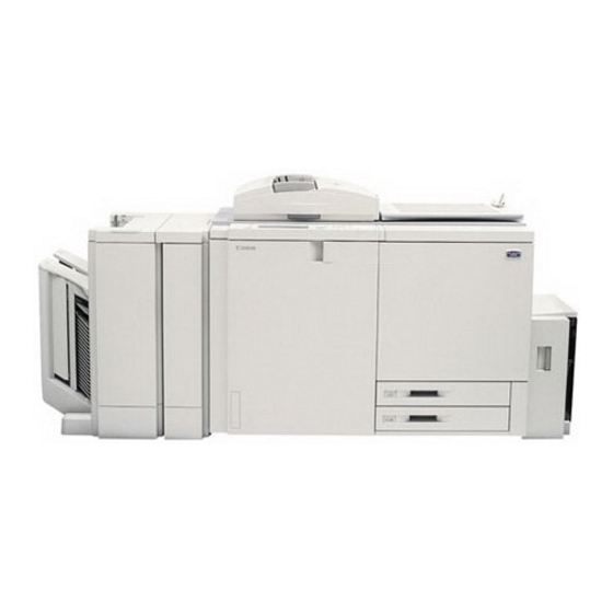
System Configuration
Diagram showing the system configuration of the Color Laser Copier 1000/1000S/3100 and its optional devices.
Chapter 1 General Description
Features
Highlights the key features of the CLC1000, including speed, paper capacity, and creative functions.
Specifications
Details the technical specifications of the copier's type and mechanisms.
Performance
Outlines the performance specifications, including copy size, paper type, and margins.
Laser and Safety Measures
Provides information on DHHS and CDRH compliance, and safety precautions for handling the laser unit.
Names of Parts
Identifies and labels external parts of the copier, including the control panel and paper deck.
Chapter 2 Copying Process
Image Formation
Explains the eight steps involved in the image formation process of the copier.
Auxiliary Process
Details auxiliary processes such as pre-primary charging and transfer belt cleaning.
Limitations
Discusses the inherent limitations of the electrophotographic process and the copier's characteristics.
Chapter 3 Operation and Timing
Basic Mechanisms
Explains the functional construction and electrical circuitry of the CLC1000.
Original Exposure System
Covers functions related to exposing originals and directing reflected light to the CCD.
Image Processing System
Details the system for processing digital video signals from analog video signals.
Laser Exposure System
Explains the laser unit, scanning unit, and BD detection PCB for scanning direction synchronization.
Image Formation System
Covers functions like drum surface potential control, gradation correction, and transfer current control.
Pick-up/Feeding Assembly
Describes the paper feeding system, including cassettes, multifeeder, and paper deck operations.
Transfer Unit
Explains the transfer unit's construction and functions, including paper retention and toner transfer.
Fixing/Delivery Assembly
Details the loads driven by the fixing motor, including rollers, web, and oil application.
Control Panel
Explains the functions of the control panel, including data communication, LCD processing, and touch switch input.
Editor
Describes the static type editor for input coordinate adjustment and area recognition.
Fans
Shows locations and functions of fans for ozone exhaust, toner drawing, and part cooling.
Power Supply
Details the DC power supply routes and protection mechanisms for preventing malfunctions.
Chapter 4 Mechanical System
Externals and Controls
Identifies and illustrates external covers and controls of the machine.
Drive System
Details the drum drive, developing motor, pick-up drive, scanner drive, and fixing drive assemblies.
Pick-Up/Feeding System
Covers the paper deck, pick-up assembly, multifeeder, duplexing unit, and pre-fixing/pre-duplexing feeding assemblies.
Transfer Unit
Explains the construction and removal procedures for the transfer unit components.
Exposure System
Details the original exposure system, including scanning lamp and CCD unit removal.
Laser System
Covers laser unit removal, lens scanner motor removal, and image position correction mirror unit.
Hopper System
Provides instructions for removing and installing hopper assemblies and toner level sensors.
Charging System
Explains the primary charging assembly, separation/pre-fixing assembly, and process unit system.
Process Unit System
Details procedures for sliding out, removing, and installing process unit components like developing assemblies.
Fixing System
Covers the removal and installation of fixing assembly parts, including rollers, heaters, and cleaners.
Electrical System
Details the removal and installation of electrical components like PCBs, sensors, and transformers.
Chapter 5 Installation
Selecting the Site
Guidelines for choosing an appropriate installation site, considering power supply, environment, and levelness.
Installation
Provides step-by-step instructions for unpacking the machine and its accessories.
Removing the Fixings, Supplying Fixing Oil, and Changing the Voltage Rating
Details procedures for removing shipping fixings, supplying oil, and setting voltage for North American models.
Supplying Toner
Instructions on how to properly shake and install toner containers for Y, M, C, and Bk colors.
Supplying Starter
Step-by-step guide for supplying starter to the developing assembly for each color.
Preventing Deformation of Externals
Procedures to protect external parts from deformation during handling and installation.
Mounting the Belt Retaining Members
Instructions on how to fit and secure belt retaining members to the machine's base plate.
Mounting the Developing Bias Assembly Protection Member
Steps for securing the developing bias assembly protection member using screws and ensuring proper belt tension.
Installing the Paper Deck for CLC1000
Procedure for installing the paper deck, including cover removal and cable connections.
Installing the Paper Deck-H1
Installation steps for the Paper Deck-H1, including cover removal and side guide plate adjustment.
Checking the Operation of the Paper Deck
Procedures for checking paper pickup, registration, and image quality after paper deck installation.
Installing the Original Tray
Instructions for installing the original tray on both the right and left sides of the copier.
Installing the Control Card V
Steps for installing the control card, including connecting harnesses and securing the control panel.
Chapter 6 Maintenance and Servicing
Periodically Replaced Parts
Lists parts that require periodic replacement, their part numbers, quantity, life, and remarks.
Consumables and Durables
Details consumables and durable parts based on the copier's hard counter.
Scheduled Servicing Procedure
Outlines the steps and checks required for scheduled maintenance every 25,000 copies.
Scheduled Maintenance Chart
Provides a chart detailing maintenance tasks for various units based on copy count or time.
Chapter 7 Troubleshooting Image Faults/Malfunctions
Standards and Adjustments
Defines standards for image-related parts like non-image width and image margin, with adjustment procedures.
Troubleshooting Image Problems
Provides a guide to identifying and resolving common image faults based on cause and checks.
Troubleshooting Feeding Problems
Details common feeding problems such as jams and wrinkles, with their causes and corrective actions.
Arrangement and Function of Electrical Parts
Illustrates and lists the arrangement and function of various electrical components like sensors, PCBs, and motors.
Service Mode
Explains how to start, select items, and end service mode, including display and adjustment functions.
Self Diagnosis
Lists error codes (E000-E076) with their causes, checks, and recommended actions for self-diagnosis.
Appendix
General Timing Chart
Visual representation of the timing of various machine operations during the copying process.
Signals and Abbreviations
Lists and defines signals and abbreviations used throughout the manual.
General Circuit Diagram
Provides comprehensive circuit diagrams for various major units of the DC controller.
DC Controller Circuit Diagram
Detailed circuit diagrams for the DC controller, showing connections to various components.
Reader Controller Circuit Diagram
Circuit diagrams illustrating the reader controller and associated components like the IPC interface.
CCD Driver Circuit Diagram
Circuit diagrams for the CCD driver, detailing connections to various analog processor and image processor components.
HVT Circuit Diagram
Circuit diagrams for the High-Voltage Transformer (HVT) units, detailing their connections and functions.
Special Tools
Lists special tools required for servicing the machine, including their part numbers and rank.
Solvents and Oils
Details solvents and oils used for cleaning and lubrication, including chemical formulas and handling precautions.
Need help?
Do you have a question about the 3100 and is the answer not in the manual?
Questions and answers