Denon PMA-2000IVR Operating Instructions Manual
Denon integrated stereo amplifier operating instructions pma-2000ivr
Hide thumbs
Also See for PMA-2000IVR:
- Brochure & specs (2 pages) ,
- Operating instructions manual (19 pages) ,
- Service manual (36 pages)
Table of Contents
Advertisement
INTEGRATED STEREO AMPLIFIER
PMA-2000IVR
OPERATING INSTRUCTIONS
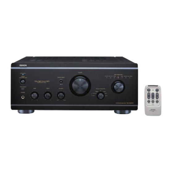
B
MUTE/STANDBY
POWER
¢ ON/STANDBY
£
OFF
REMOTE SENSOR
BASS
PHONES
"SERIAL NO.
PLEASE RECORD UNIT SERIAL NUMBER ATTACHED TO THE REAR OF THE
CABINET FOR FUTURE REFERENCE"
VOLUME
SOURCE DIRECT
¢ ON
£
OFF
TREBLE
BALANCE
TAPE-1 2
COPY
LEFT
RIGHT
INPUT SELECTOR
TAPE-2/MD TAPE-1/CD-R
PHONO
CD
TUNER
DVD/AUX-1 AUX-2/P. DIRECT
REC OUT SELECTOR
CD
TUNER
PHONO
AUX-1
1
AUX-2
AMP
POWER
MUTING
9
8
TRACK
FUNCTION
VOLUME
3
2
1
PAUSE
STOP
PLAY
CD
B
REMOTE CONTROL UNIT
RC-858
Advertisement
Table of Contents

Related Manuals for Denon PMA-2000IVR


Summary of Contents for Denon PMA-2000IVR
-
Page 1: Operating Instructions
INTEGRATED STEREO AMPLIFIER PMA-2000IVR OPERATING INSTRUCTIONS MUTE/STANDBY POWER ¢ ON/STANDBY £ REMOTE SENSOR BASS TREBLE PHONES “SERIAL NO. PLEASE RECORD UNIT SERIAL NUMBER ATTACHED TO THE REAR OF THE CABINET FOR FUTURE REFERENCE” VOLUME INPUT SELECTOR TAPE-2/MD TAPE-1/CD-R PHONO TUNER DVD/AUX-1 AUX-2/P. -
Page 2: Safety Precautions
SAFETY PRECAUTIONS CAUTION RISK OF ELECTRIC SHOCK DO NOT OPEN CAUTION: TO REDUCE THE RISK OF ELECTRIC SHOCK, DO NOT REMOVE COVER (OR BACK). NO USER-SERVICEABLE PARTS INSIDE. REFER SERVICING PERSONNEL. The lightning flash with arrowhead symbol, within an equilateral triangle, is intended to alert the user to the presence of uninsulated “dangerous voltage”... -
Page 3: Safety Instructions
SAFETY INSTRUCTIONS Read Instructions – All the safety and operating instructions should be read before the product is operated. Retain Instructions – The safety and operating instructions should be retained for future reference. Heed Warnings – All warnings on the product and in the operating instructions should be adhered to. -
Page 4: Table Of Contents
NOTE: 1. Always keep the POWER switch on the main unit turned on. 2. Turn the power on and off from the remote control unit. 3. Unplug the power cord when you do not plan to use the unit for a long period of time. - Page 5 Power switch (POWER) When the power switch is turned ON ( MUTE/STANDBY LED lights. When the power switch is turned ON, power is supplied to the unit. It takes a few seconds after the power is turned on for the unit to warm up. This is due to the built-in muting circuit that eliminates noise during the on/off operation.
-
Page 6: Rear Panel
Rear Panel Inputs terminals (INPUTS) These are input terminals for CD players, turntables, AM/FM tuners, tape decks or other playback components. NOTE: The PHONO input terminals are equipped with a short pin-plug. Remove this plug to connect a record player. Store the removed short pin-plug in a safe place so as not to lose it. -
Page 7: Connections
Ground terminal (SIGNAL GND) Connect the turntable’s ground wire here. NOTE: This terminal is used to reduce noise when a turntable, etc., is connected. It does not provide grounding. Cartridge selection switch (CARTRIDGE) This switch is set according to the type of player cartridge to be used. - Page 8 Cautions on Connections • Do not plug in the power cord until all connections are completed. • Be sure to connect the left and right channels properly. • Insert the plugs securely. Incomplete connections can result in noise. • Use the SWITCHED AC OUTLETS to plug in audio components.
-
Page 9: Operation
3. Start recording with the component connected to “TAPE- 1/CD-R” or “TAPE-2/MD”. • In the PMA-2000IVR, the REC OUT signal and the speaker (headphone) signal are output via separate circuits so that knobs and switches related to the tone and volume have no effect what ever on the sound that is recorded. -
Page 10: Remote Control Operation
This will cause misoperation. Besides being able to operate the PMA-2000 IVR Integrated-amplifier with this Remote Control Unit, you can also operate a DENON CD player from this handy Remote Control Unit. Notes on Battery Usage •... - Page 11 • The RC-858 Remote Control Unit can control CD players manufactured by DENON. • Note that operation may not be possible for some models. CAUTION: Some of the functions of the PMA-2000IVR can also be controlled with the remote control units included with other DENON pre- main amplifiers. CD player Block Use these to control the CD player connected to the PMA-2000IVR.
-
Page 12: Troubleshooting
5 TROUBLESHOOTING Check the following before assuming there is a problem with the set. 1. Are all connections proper ? 2. Is the set being operated as described in the operating instructions ? 3. Are the speakers and input components being operated properly ? If the set does not seem to be operating properly, check the points listed below. -
Page 13: Specifications
6 SPECIFICATIONS • POWER AMPLIFIER SECTION Rated Output Power: Both channel driven (8 /ohms Load) 80 W + 80 W 20 Hz to 20 kHz, T.H.D. 0.07 % (4 /ohms Load) 160 W + 160 W DIN, 1 kHz, T.H.D. 0.7 % Total Harmonic Distortion: 0.01 % (–3 dB at rated output, 8 /ohms) (1 kHz) Input Sensitivity/Input Impedance:... - Page 14 MEMO...
- Page 15 MEMO...
- Page 16 16-11, YUSHIMA 3-CHOME, BUNKYOU-KU, TOKYO 113-0034, JAPAN Telephone: (03) 3837-5321 Printed in Japan 511 3917 001...
Need help?
Do you have a question about the PMA-2000IVR and is the answer not in the manual?
Questions and answers