Table of Contents
Advertisement
e
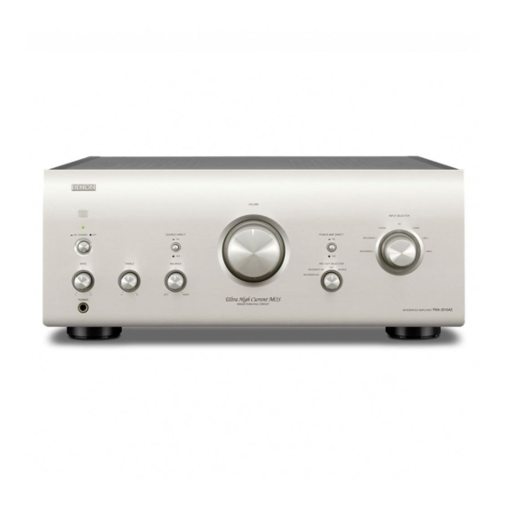
PMA-2020AE
• For purposes of improvement, specifications and design are subject to change without notice.
• Please use this service manual with referring to the operating instructions without fail.
• Some illustrations using in this service manual are slightly different from the actual set.
S0569-1V02DM/DG1210
SERVICE MANUAL
MODEL
INTEGRATED AMPLIFIER
Copyright 2012 D&M Holdings Inc. All rights reserved.
WARNING: Violators will be prosecuted to the maximum extent possible.
JP
E3
E2
P
e
D&M Holdings Inc.
Ver. 2
Please refer to the
MODIFICATION NOTICE.
EK
EA
E1C E1K EUT
P
Advertisement
Table of Contents

Related Manuals for Denon PMA-2020AE


Summary of Contents for Denon PMA-2020AE
- Page 1 MODIFICATION NOTICE. SERVICE MANUAL MODEL E1C E1K EUT PMA-2020AE INTEGRATED AMPLIFIER • For purposes of improvement, specifications and design are subject to change without notice. • Please use this service manual with referring to the operating instructions without fail. • Some illustrations using in this service manual are slightly different from the actual set.
-
Page 2: Table Of Contents
CONTENTS ABOUT THIS MANUAL .............3 What you can do with this manual ..........3 Using Adobe Reader (Windows version) ........4 SAFETY PRECAUTIONS ............6 NOTE FOR SCHEMATIC DIAGRAM .........7 NOTE FOR PARTS LIST ............7 TECHNICAL SPECIFICATIONS ..........8 DIMENSION ................8 DISASSEMBLY ................11 1. REMOTE I/O UNIT ..............12 2. -
Page 3: About This Manual
ABOUT THIS MANUAL Read the following information before using the service manual. What you can do with this manual Search for a Ref. No. (phrase) Jump to the target of a schematic diagram (Ctrl+Shift+F) connector You can use the search function in Acrobat Reader to Click the Ref. -
Page 4: Using Adobe Reader (Windows Version)
Using Adobe Reader (Windows version) Add notes to this data (Sign) Magnify schematic / printed wiring board The Sign function lets you add notes to the data in this diagrams - 1 manual. (Ctrl+Space, mouse operation) Save the file once you have finished adding notes. Press Ctrl+Space on the keyboard and drag the mouse to select the area you want to view. - Page 5 Magnify schematic / printed wiring board Magnify schematic / printed wiring board diagrams - 2 diagrams - 3 (Pan & Zoom function) (Loupe Tool function) The Pan & Zoom function lets you see which part of a The Loupe Tool function lets you magnify a specific magnified diagram is being shown in a separate window.
-
Page 6: Safety Precautions
SAFETY PRECAUTIONS The following items should be checked for continued protection of the customer and the service technician. LEAKAGE CURRENT CHECK Before returning the set to the customer, be sure to carry out either (1) a leakage current check or (2) a line to chassis resistance check. -
Page 7: Note For Schematic Diagram
NOTE FOR SCHEMATIC DIAGRAM WARNING: Parts indicated by the z mark have critical characteristics. Use ONLY replacement parts recommended by the manufacturer. CAUTION: Before returning the set to the customer, be sure to carry out either (1) a leakage current check or (2) a line to chassis resistance check. If the leakage current exceeds 0.5 milliamps, or if the resistance from chassis to either side of the power cord is less than 460 kohms, the set is defective. -
Page 8: Technical Specifications
TECHNICAL SPECIFICATIONS n Power amplifier section n Overall performance Rated output power : 2-channel driving (CD → SP OUT) S/N Ratio (A network) : 80 W + 80 W (8 Ω, 20 Hz – 20 kHz, T.H.D. 0.07 %) PHONO (MM): 89 dB Dynamic power : 160 W + 160 W (4 Ω, DIN, 1 kHz, T.H.D. - Page 9 WIRE ARRANGEMENT If wire bundles are untied or moved to perform adjustment or parts replacement etc.,be sure to rearrange them neatly as they were originally bundled or placed afterward. Otherwise, incorrect arrangement can be a cause of noise generation. Wire arrangement viewed from the top Front Panel side Back Panel side...
- Page 10 Wire arrangement viewed from the bottom Front Panel side Back Panel side...
-
Page 11: Disassembly
DISASSEMBLY • Disassemble in order of the arrow of the figure of following flow. • In the case of the re-assembling, assemble it in order of the reverse of the following flow. • In the case of the re-assembling, observe "attention of assembling" it. TOP COVER REMOTE I/O UNIT Refer to "EXPLODED VIEW"... -
Page 12: Remote I/O Unit
About the photos used for "descriptions of the DISASSEMBLY" section • The direction from which the photographs used herein were photographed is indicated at "Direction of photograph: ***" at the left of the respective photographs. • Refer to the table below for a description of the direction in which the photos were taken. •... - Page 13 (2) Remove the screws. (3) Remove the screws, then remove the solder.
-
Page 14: Input Unit And Ph/Cd Ter.unit
3. INPUT UNIT and PH/CD TER.UNIT Proceeding : TOP COVER → SIDE COVER (R) → INPUT UNIT and PH/CD TER. UNIT (1) Disconnect the connector wires. (2) Remove the screws... -
Page 15: P.amp(R) Unit
4. P.AMP(R) UNIT Proceeding : TOP COVER P.AMP (R) UNIT → (1) Remove the screws. (2) Disconnect the connector wires, then remove the screws. Remove the solder... -
Page 16: Front Panel Assy
5. FRONT PANEL ASSY Proceeding : TOP COVER → SIDE COVER (L), (R) → FRONT PANEL ASSY (1) Disconnect the connector wire. N0611 Direction of photograph: C (2) Remove the screws View from bottom (3) Remove the screws (4) Loose the Cord holders, then disconnect the connector wires. -
Page 17: Bottom Cover
(5) disconnect the connector wire. Please refer to "EXPLODED VIEW" for the disassembly method of each P.W.B included in PANEL FRONT ASSY. 6. BOTTOM COVER Proceeding : TOP COVER → SIDE COVER (L), (R) → BOTTOM COVER (1) Remove the screws. -
Page 18: Ce33W==123M
7. CE33W==123M Proceeding : TOP COVER → SIDE COVER (L), (R) → BOTTOM COVER CE33W==123M → (1) Cut the wire clamp bands. Direction of photograph: D (2) Remove the screws. (3) Remove the screws. -
Page 19: Idling Adjustment
IDLING ADJUSTMENT DC Voltmeter Power Trans R582 R581 Power Trans 8U-110133-2 8U-110133 -1 Power Amp P.W.B. (R) Power Amp P.W.B. (L) Main Volume Setup IDLING CURRENT Lay the unit at an ordinary position away from a direct current from an air condition or fan. Do the adjustment at a Setup temperature between 15°C (59°F) and 30°C (86°F). -
Page 20: Trouble Shooting
TROUBLE SHOOTING 1. The power can not be turned on. (Power indication LED does not light.) Check the insertion of the 8U-110132-6 AC UNIT. Check the insertion of the 8U-110132-2 UCOM UNIT. Check whether power is being supplied to the Broken wire in standby Power not supplied. -
Page 21: The Power Turned On, But A Sound Does Output Normally. (Single Channel)
2.4. Power indicator LED is lit normally (green or Check each connector. orange). Check the voltage of each department. Check the operation of the switching relay and speaker relay. Check the Signal line. 3. The power turned on, but a sound does output normally. (Single channel) Power indicator LED is lit normally (green or Check each connector. -
Page 22: Block And Level Diagram
BLOCK AND LEVEL DIAGRAM NETWORK... -
Page 23: Wiring Diagram
WIRING DIAGRAM... -
Page 24: Printed Wiring Boards
PRINTED WIRING BOARDS EQ/INPUT EQ/INPUT (COMPONENT SIDE) (FOIL SIDE) EQ/INPUT UNIT 8U-110132-1 63101013210AD C714 R714 S701 JV78 R738 R740 R736 L704 L702 R726 R730 C720 R718 JV112 R720 R732 R728 D702 JV106 JV114 C716 Q706 R724 Q702 Q704 Z703 C702 R734 C724 C722... - Page 25 VOLUME VOLUME INPUT_SEL_SW INPUT_SEL_SW (COMPONENT SIDE) (FOIL SIDE) (COMPONENT SIDE) (FOIL SIDE) Z902 N0350 N0570 D952 D951 D953 B302 C343 D956 D954 C341 C342 JV173 D957 D955 R901 R919 R902 R918 R917 R912 R904 R910 R908 R351 JV174 R906 R916 R914 JV177 S901...
- Page 26 POWER AMP (L) POWER AMP (L) POWER_SW POWER_SW (COMPONENT SIDE) (FOIL SIDE) (COMPONENT SIDE) (FOIL SIDE) 8U-110133-1 L-ch POWER AMP (L) UNIT B513 N501 C545 C537 R585 N913 Q515 C521 C503 POWER SW UNIT C509 8U-110133-5 8U-110133-3 Q529 R533 Q509 D513 C515 N911...
- Page 27 DIODE DIODE (COMPONENT SIDE) (FOIL SIDE) P.LED P.LED (COMPONENT SIDE) (FOIL SIDE) B812 C810 C802 C801 C809 C808 Z903 JV25 15.0 Z801 Q903 C806 C805 (WHT) (RED) D801 (YEW) (BLK) (BLU) 12.5 17.5 B810 R942 B813 B814 B809 B808 C905 8U-110133-7 R941 (GND)
- Page 28 POWER_SUPPLY POWER_SUPPLY (COMPONENT SIDE) (FOIL SIDE) Z801 C838 C837 F822 12.5 Z811 15.0 C831 C832 JV34 12.5 Q822 Q824 Q823 Q821 R822 R821 R823 R824 C825 C826 C829 C835 C836 C830 C827 C833 C834 C828 JV33 POWER SUPPLY UNIT 8U-110134-1 C843 C842 C841...
-
Page 29: Schematic Diagrams (1/5)
+16V Z101 R741 R922 N1311 M3-SIDE 1.8K U701 N1311 00D2051034023 8U-110132-3 +7.3V SA5532ADR R923 13P-PHs Z902 C711 C715 1.8K R715 R731 R733 STYLE-PIN (1/2) VOLUME UNIT +7.3V 3300P 00D2050452017 10/50 Z702 C717 LD901-907 SEL2915 A Q902 VINYL_WIRE 1200P Q901 KRA102S KRA102S C719 C721... -
Page 30: 110132_2
Z60 5 RADIATOR 00D4170476010 N0410 N0410 D617 4P-EH(IM) 11EQS10 +14V U605 NJM7812FA +12V +12V R642 D618 SHORT 11EQS10 AVDD C612 0.01 C618 B602 N0670 OPEN OPEN. Q618 6P-PH KTB631K(Y ) +12V RELAY B +12V P.DIRECT_T P.DIRECT PRE_OUT_T R643 H/P MUTE 4.7K U604 D619... -
Page 31: 110133_1
8U-110133-1 POWER AMP (L) UNIT 8U-110133-2 POWER AMP (R) UNIT 8U-110133-3 MULTIPLYER L UNIT 8U-110133-4 MULTIPLYER R UNIT 8U-110133-5 POWER SW. UNIT 8U-110133-6 TONE UNIT 8U-110133-7 DIODE UNI 8U-110133-8 POWER LED UNIT 8U-110133-9 PHONO/CD TERMINAL UNIT 8U-110133-10 REC./PRE OUT UNIT 8U-110133-11 REMOTE I/O UNIT 8U-110133-12 DIRECT SW. -
Page 32: 110133_2
1U-110133-10 REC/PREOUT UNIT K501 8U-110133-13 643010073204S K306 -15.8V PHONE JACK UNIT PHONE-JACK-BOARD(9P ) 4P-PINJACK VR203:BASS (1/2) VR201 U201 N0630 R223 NJM2082DD R207 C205 N0630 10/50(RA3) 6P-EH(IM) R201 R217 RECORDER1 C213 REC1OUT_L 3.3K 0.1/50(RA3) C209 R211 15K REC2OUT_L R203 CF0.033J Lc h R219 22K VR202:TREBLE VR201:... -
Page 33: 110134_1
+28V +28V F821 D821 C425 2SK209(GR) 2SK209(GR) 3.15A(25RF) KTC4370A(0/Y) FCH20A15 CQ0.01(LP) Q827 +44V KTC4370A(0/Y) +16V Q823 Q821 Q825 R443 1SS133 100(1W)_AMRA R825 Q437 1SS133 +26.7V 2SK215 +27.3V R823 D425 R821 N0250 1K(AMRS) 1K(AMRS) 2P-VHws D423 +16.6V + 28.6V S402 +26.7V POWER TRANS N0520 Q423... -
Page 34: Exploded View
EXPLODED VIEW 45 46 2-11 2-10 103 31 2-12 2-13 WARNING: Parts marked with this symbol have critical characteristics. Use ONLY replacement parts recommended by the manufacturer. 印の部分は安全を維持するために重要 な部品です。従って交換時は必ず指定の 部品を使用してください。... -
Page 35: Parts List Of Exploded View
CARD SPACER (L=20) 2-13 PHONE JACK UNIT P.W. SPACER 9S4021027300D FRONT PANEL SUB ASSY FLAT AMP UNIT P.W.B. ASSY FRONT PANEL FLAT AMP UNIT DENON BADGE POWER SUPPLY UNIT LENS LENS FRONT CHASSIS KNOB GUIDE(L) BUSH KNOB GUIDE (R) FLEXIBLE BUSH... - Page 36 Ref. No. Part No. Part Name Remarks Q'ty New Ref. No. Part No. Part Name Remarks Q'ty New TRANS LABEL(E) ★ 308 4P EH-EH CON CORD CN041 HIMELON SHEET ★ 309 5P EH-EH CON.CORD CN054 00D4411945019 PLATE (T/C) ★ 310 5P EH-EH CON CORD CN055 UL TUBE (11.1) BK...
-
Page 37: Packing View
PACKING VIEW 206 207 208 209 PARTS LIST OF PACKING & ACCESSORIES z Parts indicated by "nsp" on this table cannot be supplied. z The parts listed below are only for maintenance, might differ from the parts used in the unit in appearances or dimensions. Note: The symbols in the column "Remarks"... -
Page 38: Semiconductors
SEMICONDUCTORS Only major semiconductors are shown, general semiconductors etc. are omitted from list. The semiconductors which described a detailed drawing in a schematic diagram are omitted from list. 1. IC's TMP86FH47BUG (U601) TMP86FH47BUG Terminal Functions Pin No. Port Name Function to GND x'tal (8MHz) XOUT... - Page 39 volume up volume down INT2 remocon input INT1 Power off (power failure) PDO3/PWM3 timer reset AIN0 Model switch AIN1 sp output A/B (not use) AIN2 rec out selector (not use) AIN3 function A AIN4 STOP2 muting AIN5 STOP3 sp output A (not use) AIN6 STOP4 NETWORK LED/relay drive...
- Page 40 LB1930MC (U602) Block Diagram and Sample Application Circuit C1=1µF V CC 60kΩ OUT1 60kΩ OUT2 S-GND P-GND NJU7181RB1 (U303, U304) Symbol Function AC Input AMP_OUT Amplifier Output TRIN External Trigger Input Ground CAP_D Delay Time Capacitor RES_D Delay Time Resister DC Output Supply Voltage...
-
Page 41: Parts List Of P.c.b. Unit
PARTS LIST OF P.C.B. UNIT z Parts indicated by "nsp" on this table cannot be supplied. z The parts listed below are only for maintenance, might differ from the parts used in the unit in appearances or dimensions. Note: The symbols in the column "Remarks" indicate the following destinations. E3 : U.S.A. - Page 42 Ref. No. Part No. Part Name Remarks Q'ty R0717,0718 00D2412468966 RD14B2E222JT(AMRS) R0719,0720 00D2412465927 RD14B2E820JT(AMRS) R0721,0722 00D2412467967 RD14B2E821JT(AMRS) R0723,0724 00D2412475975 RD14B2E225JT(AMRS) R0725,0726 00D2412471982 RD14B2E473JT(AMRS) R0727,0728 00D2412469923 RD14B2E392JT(AMRS) R0729,0730 00D2412463987 RD14B2E220JT(AMRS) R0731,0732 00D2412466926 RD14B2E221JT(AMRS) R0733,0734 00D2412467909 RD14B2E471JT(AMRS) R0735,0736 00D2412474921 RD14B2E474JT(AMRS) R0737,0738 00D2412479997 RD14B2E6R8JT(AMRS) R0739,0740 00D2412473906 RD14B2E154JT(AMRS) z R0741,0742...
- Page 43 Ref. No. Part No. Part Name Remarks Q'ty C0643 00D2544573949 CE04W1H010MT(RA3) C0644 00D2544573910 CE04W1HR22MT(RA3) C0645,0646 00D2544574906 CE04W1H330MT(RA3) C0701,0702 133050078489S CQ93P2D470K(FAS) E2, E1C C0703,0704 133050074524S CQ93M2E151J(LP) C0705,0706 133050075527S CQ93M2E102J(LP) C0707,0708 00D2544703706 CE04W1H101MC(RFS#A) C0709,0710 133050074500S CQ93M2E101J(LP) E2, E1C C0711,0712 133050076537S CQ93M2E332J(LP) C0713,0714 00D2544703706 CE04W1H101MC(RFS#A) C0715,0716 00D2544702956 CE04W1H100MT(RFS#A)
- Page 44 Ref. No. Part No. Part Name Remarks Q'ty z T0101 10101016700AD STANDBY TRANS E2 E2, E1C z T0101 10101016600AD STANDBY TRANS JP X0601 00MFQ08004061 CSTS MG 8MHZ TAPING(15PF) Z0101 M3 SCREW TERMINAL Z0601 STYLE PIN Z0603 STYLE PIN Z0702 VINYL WIRE Z0703 VINYL WIRE Z0902...
-
Page 45: 110133 Power Amp P.w.b. Unit Ass'y
8U-110133 POWER AMP P.W.B. UNIT ASS'Y Note: The symbols in the column "Remarks" indicate the following destinations. E3 : U.S.A. & Canada model E2 : Europe model EA : Australia model E1C : China model CIE3 : U.S.A. & Canada model BK : Black model SP : Premium Silver model Ref. - Page 46 Ref. No. Part No. Part Name Remarks Q'ty R0559,0560 00D2412468966 RD14B2E222JT(AMRS) R0565,0566 00D2442693947 RS14B3A220JNBST AMRA R0567,0568 00D2412470967 RD14B2E153JT(AMRS) R0569-0572 00D2412470941 RD14B2E123JT(AMRS) R0573,0574 00D2412470925 RD14B2E103JT(AMRS) R0575,0576 00D2412471940 RD14B2E333JT(AMRS) z R0577 00D2442693989 RS14B3A470JNBST AMRA R0581,0582 16101000643AS V06QB502T R0585,0586 00D2442698007 RS14B3D100JNBF(AMRA) CAPACITORS GROUP C0201 00D2544702956 CE04W1H100MT(RFS#A)
- Page 47 Ref. No. Part No. Part Name Remarks Q'ty N0640 B6B-EH-TS (LF)(SN) 6P RADIAL TAPING JST N0650 S6B-PH-K-S (LF)(SN) N0651 B6B-PH-K-S (LF)(SN) N0811 B8B-EH N0911-0914 M3 SCREW TERMINAL N1011 B10B-EH N1211 B12B-PH-K-S (LF)(SN) z S0101 66105000300AS POWER SWITCH (TV-5) S0201 665010010005D 1P PUSH SWITCH(6-2) S0251 00D2140127003...
-
Page 48: 110134 Flat Amp P.w.b. Unit Ass'y
8U-110134 FLAT AMP P.W.B. UNIT ASS'Y Note: The symbols in the column "Remarks" indicate the following destinations. E3 : U.S.A. & Canada model E2 : Europe model EA : Australia model E1C : China model CIE3 : U.S.A. & Canada model BK : Black model SP : Premium Silver model Ref. - Page 49 Ref. No. Part No. Part Name Remarks Q'ty New C0473-0476 00D2544703777 CE04W1H470MC(RFS#A) C0827,0828 133050076599S CQ93M2E103J(LP) C0829,0830 00D2544703777 CE04W1H470MC(RFS#A) C0831,0832 00D2544703748 CE04W1H102MC(RFS#A) C0833,0834 133050076599S CQ93M2E103J(LP) C0835,0836 00D2544703777 CE04W1H470MC(RFS#A) C0837,0838 00D2544703748 CE04W1H102MC(RFS#A) C0839,0840 133050076599S CQ93M2E103J(LP) C0841-0844 00D2544703748 CE04W1H102MC(RFS#A) OTHERS PARTS GROUP z F0821,0822 00D2061093012 FUSE 25RF 3.15A F006 N0250...
- Page 50 Personal notes:...
Need help?
Do you have a question about the PMA-2020AE and is the answer not in the manual?
Questions and answers