Table of Contents
Advertisement
Quick Links
Introduction
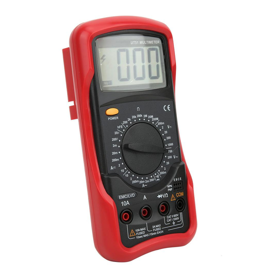
Digital Multimeter UT50 series (hereafter
referred to as "the Meter") are 2000-count
hand-held instruments featuring stable
performance, versatile functions, high degree
of reliability&accuracy. They are designed
with large-scale integrated circuits, dual
integral A/D converter as well as overloaded
protection. The series can measure AC/DC
voltage, AC/DC current, resistance,
capacitance, frequency, temperature, diode
and continuity, making the series a perfect
tool for users.
Unpacking Inspection
Unpack the carton and take out the Meter. Check
the following accessories for any missing or
damaged component. Please contact your
dealership immediately if any missing or
damaged component is found.
Operating Manual------1pc
Test Leads --------------1 pair
WRN-01B Thermocouple----1set
(For UT53,UT55 Only)
Holster (Optional)
Safety Information
UT50 Series are designed and manufactured in
compliance with: IEC61010, CAT 1000V, CAT
600V and CAT 300V, Double Insulation and
Pollution Degree.
Warnings
Use the meter as specified in the manual,
otherwise the protection offered by the Meter
may be impaired.
it may cause electric shock.
insulation or broken wires.
terminals and ensure good contact between
them.
the Meter, otherwise it may cause electric
shock or damage to the Meter.
model or similar electrical specifications.
voltage above 1000V between COM and
grounding.
above 60VDC or 30VAC RMS.
batteries as soon as
appears.
"
"
Shut off the power timely after the measurements
complete. Take out the batteries if not used for
a long time.
temperature, high moisture. The performance
of the Meter may be compromised if
moisture-affected.
injury, do not alter internal wiring randomly.
Caution
Your Meter's Features
32 ranges.
Liquid Crystal Display, digits height is 27mm.
Overload display l.
Maximum display 1999 (3 1/2 digit).
Full range overload protection.
Auto-Power Off (For UT53, UT54 and UT55
ONLY).
Temperature:
o
o
0
F
Operating:0
to 40
(32
to 104
C
C
o
o
0
F
Storing:-10
to 50
(14
to 122
C
C
Altitude:
Operating: 2000m
Storing: 10000m.
Relative Humidity:Max. relative humidity
o
80% for temperature up to 31
decreasing
C
linearly to 50% relative humidity at 40
Low Battery display
.
"
"
Battery Type: 9V NEDA 1604 or 6F22 or 006P
Strap for easy carry.
Tilt stand design, three observation angles,
is in favor of reading display.
Dimension: 190mm x 88mm x 34mm.
Weight: Meter only(excluding test leads)
about 270g .Meter + holster + tilt stand
about 550g.
Specifications
Accuracy is specified for one year after calibration,
at operating temperatures 23
o
+/- 5
o
, with relative
C
C
humidity at < 75%.Accuracy specifications take
the form of:+/- (a% readings +digits )
Direct Current Voltage (DC Voltage)
Accuracy
Range Resolution
UT51 UT 52 UT53 UT54 UT55
200mV
100μV
2V
1mV
(0.5% +1)
20V
10mV
200V
100mV
1000V
1V
(0.8% +2)
Overload protection: 250VDC or AC RMS for
200mV range. 750VRMS or 1000Vp-p for other
ranges.
Alternating Current Voltage (AC Voltage)
Accuracy
Range Resolution
UT51 UT 52 UT53 UT54 UT55
(1.2% +3)
200mV
100μV
2V
1mV
20V
10mV
(0.8% +3)
200V
100mV
(1.2% +3)
750V
1V
Frequency: 40Hz-400Hz .
Overload protection: 250VDC or AC RMS for
200mV range. 750VRMS or 1000Vp-p for other
ranges.
Display: Average Value (RMS of Sine Wave).
Direct Current Current (DC Current)
Accuracy
Range Resolution
UT51 UT 52 UT53 UT54 UT55
μ
μ
(2%+5)
20
A
0.01
A
μ
μ
200
A
0.1
A
(0.8%+1)
μ
2mA
1
A
(0.8%+1)
μ
20mA
10
A
μ
200mA
100
A
(1.5%+1 )
2A
(1.5%+1)
1mA
(2%+5)
10A
10mA
20A
(2%+5 )
Overload protection:
For UT51:
2A, 250V fast acting fuse, φ5x20mm(below
2A range)
10A, 250V fast acting fuse,φ5x20mm(at 10A
range) .
For UT52/53/54/55:
315mA, 250V fast acting fuse, φ5x20mm (No
fuse at 20A range).
Max current input :
For UT51: 10A (The measurement time for high
current should be less than 10 seconds, and
the interval time between two measurements
should be greater than 15 minutes.
For UT52/53/54/55: 20A (The measurement
time for high current should be less than 15
seconds, and the interval time between two
measurements should be greater than 15
minutes.
Alternating Current Current (AC Current)
Range Resolution
μ
μ
200
A
0.1
A
μ
2mA
1
A
μ
20mA
10
A
μ
0
200mA
100
A
F
).
2A
1mA
0
F
).
10A
10mA
20A
Overload protection:
For UT51:
2A, 250V fast acting fuse, φ5x20mm(below 2A range)
10A, 250V fast acting fuse,φ5x20mm(at 10A range) .
For UT52/53/54/55:
o
C.
315mA, 250V fast acting fuse,φ5x20mm (No fuse
at 20A range).
Max current input :
For UT51: 10A (The measurement time for high
current should be less than 10 seconds, and the
interval time between two measurements should be
greater than 15 minutes.
For UT52/53/54/55: 20A (The measurement time
for high current should be less than 15 seconds, and
the interval time between two measurements should
be greater than 15 minutes.
Measuring voltage drop: 200mV for full ranges.
Display: Average Value (RMS of Sine Wave ) .
Resistance
Range Resolution
Ω
Ω
200
0.1
Ω
Ω
2K
1
Ω
Ω
20K
10
Ω
Ω
200K
100
Ω
Ω
2M
1K
Ω
Ω
20M
10K
Ω
Ω
200M
100K
Voltage at open circuit: 700mV (200M
open circuit voltage around 3V) .
Overload protection: 250VDC or AC RMS for all
ranges.
Ω
Caution: At 200M
circuit the LCD normally display 10 digits is normal,
deduct the 10 digits from the measured reading
during measuring.
Capacitance
Range Resolution
2nF
1pF
20nF
10pF
200nF
100pF
μ
2
F
1nF
μ
20
F
10nF
Testing signal: around 400Hz 40mVrms
Frequency
Range Resolution
2kHz
1Hz
20kHz
10Hz
Accuracy
UT51 UT 52 UT53 UT54 UT55
(1.8%+3)
(1%+3)
(1%+3)
(1.8%+3)
(1.8%+3)
(3%+7)
(3%+7 )
Accuracy
UT51 UT 52 UT53 UT54 UT55
(0.8% +3)
(0.8% +1)
(1% +2)
[5%(-10) +10]
Ω
range,
range, as test lead is short
Accuracy
UT51 UT 52 UT53 UT54 UT55
(4% +3)
Accuracy
UT51
UT52
UT53
UT54 UT55
(2%+5)
(1.5%+5)
about 2.8V
about 2.8V
Advertisement
Table of Contents

Related Manuals for UNI-T UT52


Summarization of Contents
Introduction to Digital Multimeter UT50 Series
Product Overview and Features
Details the UT50 series as a 2000-count digital multimeter with versatile functions and reliability.
Unpacking and Inspection Guide
Instructions for checking meter accessories for any missing or damaged components after unpacking.
Safety Information and Warnings
Crucial safety precautions, warnings, and compliance information for operating the multimeter safely.
Meter Specifications and Capabilities
Highlights key features like range, display, overload protection, and auto-power off for UT53/54/55 models.
Technical Specifications Breakdown
Detailed specifications including accuracy, ranges, input impedance, and overload protection for various measurements.
Making Measurements with the Multimeter
Measuring DC Voltage
Procedure for measuring DC voltage, including lead connection, range setting, and cautions.
Measuring AC Voltage
Procedure for measuring AC voltage, including lead connection, range setting, and cautions.
Measuring DC Current
Procedure for measuring DC current, including lead connection, range setting, and cautions.
Measuring AC Current
Procedure for measuring AC current, including lead connection, range setting, and cautions.
Measuring Resistance
Steps for measuring resistance, including lead connection, range selection, and safety notes.
Measuring Capacitance
Instructions for measuring capacitance, including capacitor connection and stability considerations.
Measuring Frequency
Procedure for measuring frequency, including test lead connection and range setting.
Measuring Temperature
Guide to measuring temperature using the provided thermocouple probe.
Diode and Continuity Beeper Test
How to perform diode tests and continuity checks using the multimeter's beeper function.
Transistor hFE Measurement
Steps to measure the current gain (hFE) of NPN or PNP transistors.
Auto-Power Off Functionality
Explanation of the auto-power off feature designed to conserve battery life.
Maintenance and Service Procedures
General Service and Care
General advice on maintaining the precision and performance of the electrical testing instrument.
Replacing the Battery
Step-by-step instructions for safely replacing the multimeter's battery.
Replacing Fuses
Procedure for replacing the internal fuses, emphasizing the use of specified types only.
Using the Holster
Instructions on how to position and use the protective holster for various viewing angles.
Using the Carrying Strap
Guide on how to attach and utilize the carrying strap for portability.
Need help?
Do you have a question about the UT52 and is the answer not in the manual?
Questions and answers