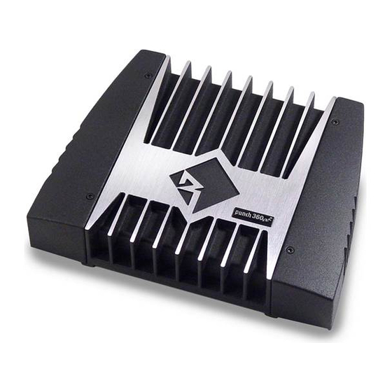
Summarization of Contents
SPECIFICATIONS
PUNCH 2-CHANNEL AMPLIFIER FEATURE CHART
Comprehensive chart detailing features and specifications across different Punch amplifier models.
INTRODUCTION
PUNCH AMPLIFIER ACCESSORY PACK
Details the accessory pack shipped with Punch 2-channel amplifiers, including mounting hardware and fuses.
MOUNTING LOCATION
Trunk Mounting
Instructions for mounting the amplifier vertically in the trunk for optimal cooling.
Passenger Compartment Mounting
Guidelines for mounting in the passenger compartment, ensuring adequate ventilation and air gap.
Engine Compartment Mounting
Warning against mounting in the engine compartment due to warranty void and poor cooling.
OPERATION
Using Passive Crossovers
Explanation of passive crossovers, their function, and types in speaker systems.
Crossover Operation
Detailed guide on adjusting the amplifier's internal crossover for High-Pass and Low-Pass filtering.
Punch Bass Adjustment
Instructions on how to use and adjust the Punch Bass feature for enhanced low-frequency response.
INSTALLATION
Connecting Audio Inputs (RCA/High Level)
Guide to connecting audio sources using RCA or high-level inputs on the amplifier.
Power and Ground Connections
Details on connecting power and ground wires, including fuse placement for amplifier models.
Bridged/Mono Mode Operation
Wiring diagrams and guidelines for operating the amplifier in bridged or mono mode.
2-Channel Mode Wiring
Wiring and configuration for standard 2-channel operation of amplifiers.
3-Channel Mode Wiring
Wiring and configuration for 3-channel operation, often involving passive crossovers.
SYSTEM DIAGRAMS
2-Way System Diagram
Diagram illustrating a typical 2-way speaker system setup with the amplifier.
3-Way System Diagram (Single Voice Coil Woofers)
Diagram for a 3-way system using single voice coil woofers and various wiring configurations.
3-Way System Diagram (Dual Voice Coil Woofers)
Diagram for a 3-way system using dual voice coil woofers and different wiring methods.
LIMITED WARRANTY INFORMATION
Length of Warranty
Details the duration of the limited warranty for electronics, source units, and speakers.
What is Covered
Specifies the scope of the warranty, including authorized dealer purchases in the USA.
How to Obtain Service
Instructions on how to get service, including obtaining an RA# and shipping information.


Need help?
Do you have a question about the Punch 250 and is the answer not in the manual?
Questions and answers