Table of Contents
Advertisement
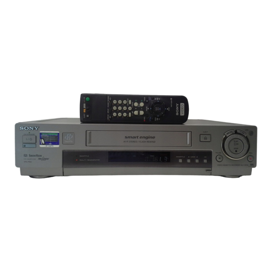
SLV-SE85/SF90/SF99
RMT-V259D/V259E/V259F/V259G/V259H/V259J/V260/V260A/V260B
SERVICE MANUAL
j
G
MICROFILM
Photo: SLV-SF90
RMT-V259F
Refer to the SERVICE MANUAL of VHS MECHANICAL
ADJUSTMENT
(9-921-647-13).
SPECIFICATIONS
VIDEO CASSETTE RECORDER
UK Model
SLV-SE85UX/SF90UX(SF)/
SF90UX(WF)/SF99UX
French Model
SLV-SE85B/SF90B(SF)/
SF90B(WF)/SF99B
German Model
SLV-SE85VC/SF90VC(SF)/
SF90VC(WF)/SF99VC
Spanish Model
SLV-SE85NP/SF90NP(SF)/
SF90NP(WF)/SF99NP
E Model
SLV-SF99EN
Irish Model
SLV-SF90EX
SR MECHANISM
for MECHANICAL ADJUSTMENTS
Advertisement
Table of Contents

Related Manuals for Sony SLV-SF99


Summarization of Contents
General VCR Operations and Setup
Getting Started with Your VCR
Covers unpacking, connecting, and initial setup procedures for the VCR.
Basic VCR Operations
Instructions for playing tapes and recording TV programs.
Advanced VCR Functions
Details on timer settings, playback speeds, editing, and audio dubbing.
SmartFile Functionality Explained
Guide to using the SmartFile feature for managing recorded tapes.
Troubleshooting Common Issues
Guidance for resolving problems and common VCR errors.
VCR Disassembly Procedures
Case and Front Panel Removal
Step-by-step guide for disassembling the unit's exterior housing.
Circuit Board Component Disassembly
Instructions for removing specific circuit boards like DM-86, FR-161.
Mechanism Deck Disassembly
Details on taking apart the SR mechanism deck.
Internal Views and Component Locations
Visual guide to the VCR's internal components and board layout.
Block Diagrams and System Architecture
Overall System Block Diagrams
Comprehensive overview of the VCR's interconnected systems.
Video System Block Diagrams
Detailed schematics of the video signal processing paths.
Servo and Motor Control Diagrams
Illustrations of the servo and mechanism control circuitry.
Memory and Audio System Diagrams
Schematics for memory management and audio signal processing.
Power Block Diagrams
Diagrams detailing the VCR's power supply circuitry.
Printed Wiring Boards and Schematics
MA-359 Board Diagrams
Wiring and schematic details for the MA-359 main board.
RP-235 Board Diagrams
Wiring and schematic details for the RP-235 REC/PB head amp board.
JK-171 Board Diagrams
Wiring and schematic details for the JK-171 Line 2 In board.
FR-161 Board Diagrams
Wiring and schematic details for the FR-161 mode control board.
NR-27 Board Diagrams
Wiring and schematic details for the NR-27 DNR, Y/C Select board.
SRV879EK Power Supply Diagrams
Wiring and schematic details for the SRV879EK power supply.
ML-17, AT-25, AT-26 Board Diagrams
Wiring details for Smart File and sensor boards.
Interface and IC Pin Descriptions
System Control Interfaces
Pinouts for VCR system control interfaces.
Mechanism Control Pin Functions
Detailed pin functions for the microprocessor.
Tuner/Timer Mode Control Pins
Pin functions for tuner and timer mode control.
Adjustments and Calibration
Mechanical Adjustments Overview
Reference to the VHS mechanical adjustment manual.
Electrical Adjustment Procedures
Steps for electrical adjustments and required equipment.
Power Supply Voltage Checks
Verification of various power supply voltages.
Video System Adjustments
Adjustments for playback level, sync AGC, and deviation.
Audio System Adjustments
Procedures for Hi-Fi and normal audio system checks.
Repair Parts List
Exploded Views of VCR Components
Visual breakdown of parts for different VCR sections.
Electrical Parts Inventory
Detailed list of electrical components and their part numbers.
Need help?
Do you have a question about the SLV-SF99 and is the answer not in the manual?
Questions and answers