Table of Contents
Advertisement
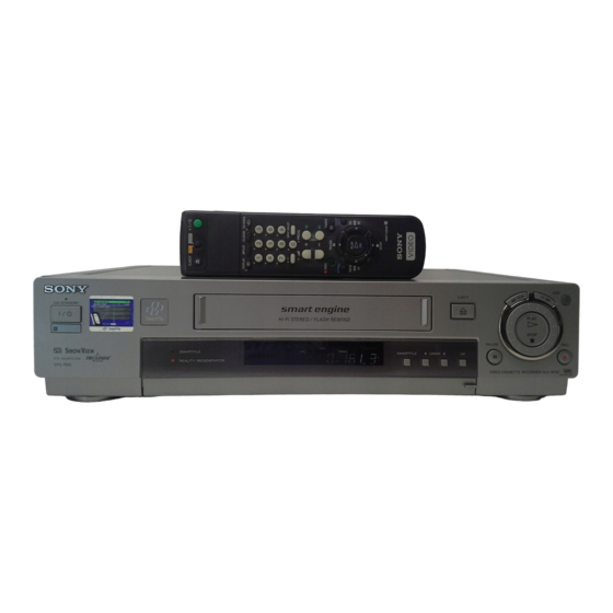
SLV-SE85/SF90/SF99
RMT-V259D/V259E/V259F/V259G/V259H/V259J/V260/V260A/V260B
SERVICE MANUAL
j
G
MICROFILM
Photo: SLV-SF90
RMT-V259F
Refer to the SERVICE MANUAL of VHS MECHANICAL
ADJUSTMENT
(9-921-647-13).
SPECIFICATIONS
VIDEO CASSETTE RECORDER
UK Model
SLV-SE85UX/SF90UX(SF)/
SF90UX(WF)/SF99UX
French Model
SLV-SE85B/SF90B(SF)/
SF90B(WF)/SF99B
German Model
SLV-SE85VC/SF90VC(SF)/
SF90VC(WF)/SF99VC
Spanish Model
SLV-SE85NP/SF90NP(SF)/
SF90NP(WF)/SF99NP
E Model
SLV-SF99EN
Irish Model
SLV-SF90EX
SR MECHANISM
for MECHANICAL ADJUSTMENTS
Advertisement
Table of Contents

Related Manuals for Sony SLV-SF90


Summarization of Contents
Safety Check-Out
Safety-Related Component Warning!!
Critical components identified by mark ! are vital for safe operation; replace with Sony parts only.
1. General
Getting Started
Initial setup procedures for the VCR, including unpacking and connections.
Basic Operations
Details fundamental VCR functions like playing tapes and recording programs.
Additional Operations
Explains advanced VCR functions beyond basic playback and recording.
SmartFile function
Describes how to use the SmartFile feature for managing recorded tapes and programs.
Additional Information
Includes troubleshooting, parts index, and menu charts for further assistance.
2. Disassembly
2-1. Case, Front Panel Block Assembly
Procedure for disassembling the VCR's case and front panel assembly.
2-2. DM-86, FR-161, JK-171, AT-26 Boards
Details disassembly steps for specific circuit boards within the VCR.
2-3. Rear Panel
Instructions for disassembling the VCR's rear panel components.
2-4. NR-27, RP-235 Boards
Disassembly steps for the NR-27 and RP-235 circuit boards.
2-5. SR Mechanism Deck
Procedure for disassembling the SR mechanism deck of the VCR.
2-6. Power Block, MA-359 Boards
Disassembly steps for the power block and MA-359 boards.
2-7. Internal Views
Illustrations showing internal views of the VCR's components.
2-8. Circuit Boards Location
Diagram showing the physical location of various circuit boards within the VCR.
3. Block Diagrams
3-1. Overall Block Diagram (1)
First part of the overall block diagram illustrating the VCR's main system connections.
3-2. Video Block Diagram (1)
First part of the video block diagram showing video signal flow and processing.
3-3. Servo Block Diagram (1)
First part of the servo block diagram illustrating motor and tape control.
3-4. Memory Block Diagram
Block diagram detailing the memory and SmartFile related circuitry.
3-5. Audio Block Diagram
Block diagram showing the audio signal processing path within the VCR.
3-6. Power Block Diagram (1)
First part of the power block diagram illustrating power supply distribution.
SECTION 4 Printed Wiring Boards and Schematic Diagrams
4-1. Frame Schematic Diagram
Schematic diagram showing the overall frame connections and major blocks.
4-2. Printed Wiring Boards and Schematic Diagrams
Details various printed wiring boards and their corresponding schematic diagrams.
MA-359 Board Schematics
Schematics and wiring diagrams for the MA-359 board, covering various functions.
RP-235 Board Schematics
Schematics and wiring diagrams for the RP-235 board.
Other Board Schematics and Wiring Diagrams
Schematics and wiring diagrams for JK-171, DM-86, FR-161, SE-90, NR-27, SRV879EK, ML-17, AT-25, AT-26 boards.
5. Interface, IC Pin Function Description
5-1. System Control — Video Block Interface (MA-359 Board IC160)
Pin assignments and functions for the video block interface on MA-359 board IC160.
5-2. System Control — Servo Peripheral Circuit Interface (MA-359 Board IC160)
Pin functions for the servo peripheral circuit interface on MA-359 board IC160.
5-3. System Control — Mechanism Interface (MA-359 Board IC160)
Pin functions for the mechanism interface on MA-359 board IC160.
5-4. System Control — System Control Peripheral Circuit Interface (MA-359 Board IC160)
Pin functions for system control peripheral circuits on MA-359 board IC160.
5-5. System Control — Audio Block Interface (MA-359 Board IC160)
Pin assignments for the audio block interface on MA-359 board IC160.
5-6. Servo/System Control Microprocessor Pin Functions (MA-359 Board IC160)
Detailed pin functions of the microprocessor on the MA-359 board IC160.
5-7. Tuner/Timer Mode Control Pin Function (FR-161 Board IC180)
Pin functions for tuner and timer mode control on FR-161 board IC180.
6. Adjustments
6-1. Mechanical Adjustment
Procedures for mechanical adjustments related to the VCR's tape transport mechanism.
6-2. Electrical Adjustment
Procedures for performing electrical adjustments and checks on the VCR.
Preparation Before Adjustment
Steps and equipment required before performing electrical adjustments.
Power Supply Check
Procedure to verify all power supply voltages meet specified values.
System Control System Adjustment
Adjustments related to the system control and clock functions.
Servo System Adjustment
Adjustments for servo system to ensure proper tape playback and compatibility.
Video System Check
Checks and adjustments for the VCR's video signal processing and playback.
Audio System Adjustment
Procedures for adjusting the VCR's audio system, including Hi-Fi and normal modes.
7. Repair Parts List
7-1. Exploded Views
Exploded views showing the VCR's physical components for parts identification.
7-1-1. Front Panel and Upper Case Section
Exploded view of the front panel and upper case assembly.
7-1-2. Chassis Section
Exploded view of the VCR's chassis section and related parts.
7-1-3. Mechanism Deck Section-1
First exploded view of the VCR's mechanism deck.
7-1-4. Mechanism Deck Section-2
Second exploded view of the VCR's mechanism deck.
7-1-5. Mechanism Deck Section-3
Third exploded view of the VCR's mechanism deck.
7-2. Electrical Parts List
List of electrical components including capacitors, resistors, and diodes.
MA-359 Board Parts
Electrical parts list specifically for the MA-359 board.
FR-161 Board Parts
Electrical parts list for the FR-161 board.
JK-171 and MA-359 Board Parts
Electrical parts list for JK-171 and MA-359 boards.
ML-17, NR-27, and RP-235 Board Parts
Electrical parts list for ML-17, NR-27, and RP-235 boards.
ML-17 Board Parts
Electrical parts list for the ML-17 board.
ML-17 and NR-27 Board Parts
Electrical parts list for ML-17 and NR-27 boards.
ML-17, NR-27, and RP-235 Board Parts
Electrical parts list for ML-17, NR-27, and RP-235 boards.
NR-27 and RP-235 Board Parts
Electrical parts list for NR-27 and RP-235 boards.
SE-90 Board Parts
Electrical parts list for the SE-90 board.
Power Block Parts
Electrical parts list for the VCR's power block.
Need help?
Do you have a question about the SLV-SF90 and is the answer not in the manual?
Questions and answers