Table of Contents
Advertisement
SLV-SE850/SF900/SF950/SF990
SERVICE MANUAL
The abbreviations of SE850/SF900/SF950/SF990 contained in this service manual
are indicated when these models are common to all their corresponding models as
given below.
Abbreviated models name
SE850
All models name
SE850B
SLV-
SE850D
SE850E
SE850G
System
Channel coverage
PA
L (B/G): SE850D,E,G/SF900D,E,G/
SF950/SF990D,E,G
VHF E2 to E12
VHF Italian channel A to H
UHF E21 to E69
CATV S01 to S05, S1 to S20
HYPER S21 to S41
SECAM (L): SE850B/SF900B/SF990B
VHF F2 to F10
UHF F21 to F69
CATV B to Q
HYPER S21 to S41
R
F output signal
UHF channels 21 to 69
Aerial out
75-ohm asymmetrical aerial socket
Tape speed
SP: PAL 23,39 mm/s (recording/playback)
NT
SC 33,35 mm/s (playback only)
SECAM 23,39mm/s (recording/playback)
(SE850B/SF900B/SF990B only)
LP: PAL11,70 mm/s (recording/playback)
NTSC 16,67 mm/s (playback only)
SECAM 11,70mm/s (recording/playback)
(SE850B/SF900B/SF990B only)
EP: NTSC 11,12 mm/s (playback only)
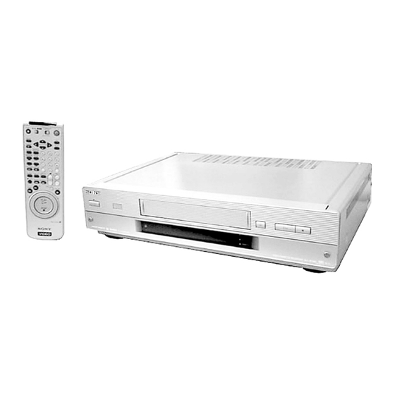
RMT-V259M/V259N/V259P/V259Q/V260C/V260D
Photo : SLV-SE990
RMT-V260D
SF900
SF950
SF990
SF900B
SF950N
SF990B
SF900D
SF990D
SF900E
SF990E
SF900G
SF990G
SPECIFICATIONS
Maximum recording/playback time
10 hrs. in LP mode (with E300 tape)
Fast-forward and rewind time
Approx. 1 min. (with E180 tape)
Inputs and outputs
i INE-1 (TV)
L
21-pin
Video input: pin 20
Audio input: pins 2 and 6
Video output: pin 19
Audio output: pins 1 and 3
DECODER/ t LINE-3 IN (SE850/SF900/SF950 only)/
LINE-4 IN (SF990 only)
21-pin
Video input: pin 20
Audio input: pins 2 and 6
LINE-2 IN
VIDEO IN, phono jack (1)
Input signal: 1 Vp-p, 75 ohms, unbalanced, sync
negative
AUDIO IN, phono jack (2)
Input level: 327 mVrms
Input impedance : more than 47 kilohms
SLV-SE850/SF900/SF950/SF990
Refer to the SERVICE MANUAL of VHS
MECHANICAL ADJUSTMENT
MECHANICAL ADJUSTMENTS. (9-921-647-11)
LINE-3 IN (SF990 only)
VIDEO IN, phono jack (1)
Input signal: 1 Vp-p, 75 ohms, unbalanced, sync
negative
AUDIO IN, phono jack (2)
Input level: 327 mVrms
Input impedance : more than 47 kilohms
LINE-2 OUT
VIDEO OUT, phono jack (1)(SF950/SF990 only)
Output signal: 1 Vp-p, 75 ohms, unbalanced, sync
negative
AUDIO OUT, phono jack (2)
Rated output level: 327 mVrms
Load impedance: 47 kilohms
Output impedance: less than 10 kilohms
— Continued on next page —
VIDEO CASSETTE RECORDER
AEP Model
UK Model
SLV-SE850/SF900/SF990
G
SR MECHANISM
for
Advertisement
Table of Contents

Related Manuals for Sony SLV-SF900


Summarization of Contents
SERVICE MANUAL
SPECIFICATIONS
Details system specifications like channel coverage and RF output.
SAFETY PRECAUTIONS
Safety Component Warning
Highlights critical components requiring careful replacement for safety.
Safety Check-Out Procedures
Steps to perform after repair to ensure set safety.
SERVICE MODE
Error Code Indication
Lists error codes and their meanings for troubleshooting.
EEPROM Data Input
Procedure for inputting data into EEPROM after replacement.
GENERAL
Getting Started Steps
Initial setup steps like unpacking and connecting the VCR.
Remote Commander Setup
Instructions for configuring the remote control.
VCR Connection Guide
Guide on how to connect the VCR to other devices.
TV Tuning Procedure
Steps to tune the TV to receive signals from the VCR.
Auto Setup Function Guide
Guide for using the VCR's automatic setup feature.
Clock Setting Instructions
Instructions for setting the VCR's internal clock.
Set-Top Box Configuration
Steps to configure the VCR with a set-top box.
Language and Channel Setup
How to select language and preset TV channels.
Program Channel Management
How to manage program channel order and disable unwanted channels.
PAY-TV/Canal Plus Decoder Setup
Instructions for connecting and setting up a decoder.
Basic VCR Operations
Instructions for common VCR operations like playing and recording.
Recording TV Programs
Guide on how to record TV programs.
ShowView System Recording
How to use the ShowView system for timer recording.
Manual Timer Recording
Manual steps for setting recording timers.
SmartFile Functionality
Information about the SmartFile feature for managing recordings.
Picture and Menu Adjustments
Steps to adjust picture settings and navigate VCR menus.
Editing and Audio Dubbing
Procedures for editing recorded tapes and performing audio dubbing.
DISASSEMBLY
Case and Front Panel Assembly
Step-by-step guide for disassembling the case and front panel.
Circuit Boards Disassembly
Instructions for disassembling specific circuit boards.
Rear Panel Disassembly
Procedures for removing the rear panel.
RP-238 Board Disassembly
Guide for disassembling the RP-238 board.
SR Mechanism Deck Disassembly
Steps to disassemble the SR mechanism deck.
Power Block and MA-388 Boards Disassembly
Instructions for disassembling power and MA-388 boards.
Internal Views and Component Locations
Visual aids showing internal component layouts and board locations.
BLOCK DIAGRAMS
Overall System Block Diagram
High-level overview of the VCR's system architecture.
Video Circuit Block Diagram
Detailed block diagram of the VCR's video processing circuits.
Servo/System Control Block Diagram
Diagram showing servo and system control functions.
Audio Circuit Block Diagram
Block diagram illustrating the VCR's audio circuitry.
Smart File System Block Diagram
Diagram of the Smart File system's architecture.
Power Supply Block Diagram
Overview of the VCR's power supply circuitry.
PRINTED WIRING BOARDS AND SCHEMATIC DIAGRAMS
Frame Schematic Diagram
Overall schematic layout of the VCR's components.
MA-388 Board Schematics
Schematics for various sections of the MA-388 board.
INTERFACE, IC PIN FUNCTION DESCRIPTION
Video Block Interface Pinout
Pin functions for system control interface to the video block.
Servo Peripheral Circuit Interface Pinout
Pin details for servo peripheral circuit interface.
Mechanism Interface Pinout
Pin functions for mechanism interface.
System Control Peripheral Interface Pinout
Pin functions for system control peripheral interface.
Audio Block Interface Pinout
Pin functions for system control interface to the audio block.
Microprocessor Pin Functions
Pinout details for the servo/system control microprocessor.
Mode Control Microprocessor Pinout
Pinout details for the mode control microprocessor.
Smart File Control Microprocessor Pinout
Pinout details for the Smart File control microprocessor.
Smart File Teletext Microcomputer Pinout
Pinout details for the Smart File teletext microcomputer.
ADJUSTMENTS AND CHECKS
Mechanical Adjustment Procedures
Procedures for mechanical adjustments.
Electrical Adjustment Preparation
Steps and equipment needed before starting adjustments.
Power Supply Voltage Checks
Procedure for checking the VCR's power supply voltages.
System Control Checks
Checks related to the system control clock oscillation.
Servo System Checks
Checks for the VCR's servo system for tape playback.
Video System Checks
Checks for the VCR's video system performance.
Audio System Adjustments and Checks
Adjustments for the VCR's audio system.
Overall Audio Output Level Check
Confirms audio output level is within specification.
REPAIR PARTS LIST
Exploded Views
Visual diagrams showing parts exploded for identification.
Front Panel and Upper Case Parts
Exploded view of the front panel and upper case components.
Chassis Parts
Exploded view of the main chassis and its components.
Mechanism Deck Parts
Exploded views of the mechanism deck.
Electrical Parts List
Lists electrical components like resistors, capacitors, and diodes.
Need help?
Do you have a question about the SLV-SF900 and is the answer not in the manual?
Questions and answers