Denon AVR-590 Owner's Manual
Denon av surround receiver user manual
Hide thumbs
Also See for AVR-590:
- Specifications (2 pages) ,
- Comparison chart (1 page) ,
- Service manual (154 pages)
Table of Contents
Advertisement
AV SURROUND RECEIVER
AVR-590
Owner's Manual
Manuel de l'Utilisateur
b The illustrations used for explaining operations in this manual show the buttons of
the remote control unit.
The same operations can be performed using the buttons with the same names on
the main unit panel.
b Les illustrations des boutons présentes dans ce manuel servent à expliquer le
fonctionnement de la télécommande.
Vous pouvez contrôler l'appareil à l'aide du bouton portant le même nom sur la
façade de l'appareil.
Advertisement
Table of Contents

Related Manuals for Denon AVR-590


Summary of Contents for Denon AVR-590
- Page 1 AV SURROUND RECEIVER AVR-590 Owner’s Manual Manuel de l’Utilisateur b The illustrations used for explaining operations in this manual show the buttons of the remote control unit. The same operations can be performed using the buttons with the same names on the main unit panel.
-
Page 2: Safety Precautions
ENGLISH FRANCAIS SAFETY PRECAUTIONS CAUTION RISK OF ELECTRIC SHOCK DO NOT OPEN CAUTION: TO REDUCE THE RISK OF ELECTRIC SHOCK, DO NOT REMOVE COVER (OR BACK). NO USER-SERVICEABLE PARTS INSIDE. REFER SERVICING TO QUALIFIED SERVICE PERSONNEL. The lightning flash with arrowhead symbol, within an equilateral triangle, is intended to alert the user to the presence of uninsulated “dangerous voltage”... - Page 3 2. IMPORTANT NOTICE: DO NOT MODIFY THIS PRODUCT This product, when installed as indicated in the instructions contained in this manual, meets FCC requirements. Modification not expressly approved by DENON may void your authority, granted by the FCC, to use the product. 3. NOTE This product has been tested and found to comply with the limits for a Class B digital device, pursuant to Part 15 of the FCC Rules.
-
Page 4: Table Of Contents
Selecting the Surround Mode ····················································37 q Playing sources according to the sources’ audio signal format/ number of channels (Standard Playback) ····································37 w Playing in a DENON original surround mode ··························38 e Direct Playback ·······································································38 r Stereo Playback ······································································39 Adjusting the Sound Field Effects (Parameter) ························39 Adjusting the sound field effects (Surround Parameter) ·············39... -
Page 5: Getting Started
Getting Started Flow of operations through playback Perform the operations leading to playback on the AVR-590 in the order shown below. Connections Installing/Setting the Speakers (vpage 10) ⇩ Connecting the Speakers (vpage 11) ⇩ Connecting Devices (vpage 12) ⇩ Turning the Power On (vpage 16) -
Page 6: Cautions On Handling
Note Wall About the Remote Control Unit In addition to the AVR-590, the included remote control unit (RC- 1120) can also be used to operate the equipment listed below. DENON system components Non-DENON system components •... -
Page 7: Part Names And Functions
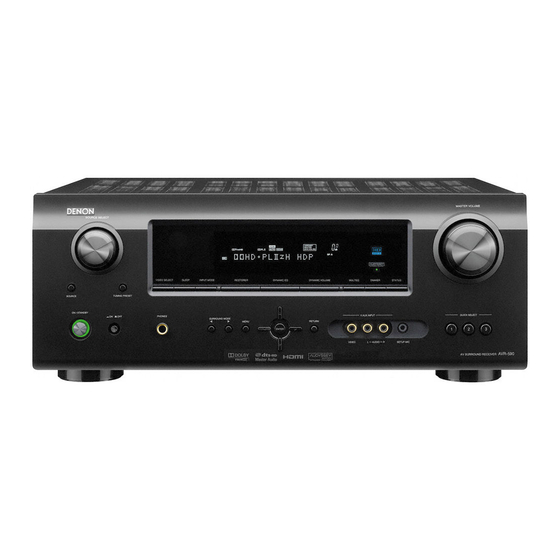
Part Names and Functions Front Panel Q0 Q1 Q2 Q4 Q5 e r t Buttons, connectors and displays only provided on the main unit Power indicator ·········································· (16) W5 HD AUDIO indicator ···································· (38) Power switch (hON jOFF) ··············· (16, 57) W6 MASTER VOLUME indicator Headphones jack (PHONES) ······················... -
Page 8: Display
ENGLISH Display Decoder indicators The indicator for the currently operating decoder lights. Input audio signal indicators Information display The input source name, surround mode, setting values and other information are displayed here. Front speaker indicator Lights when audio signals are being output from the speakers. -
Page 9: Rear Panel
Rear Panel HDMI connectors ····································································· (13) Digital audio connectors ························································· (14) VIDEO connectors ··································································· (15) PRE OUT connectors ······························································· (11) Analog audio connectors ························································ (14) FM/AM antenna terminals ······················································ (16) Speaker terminals ···································································· (11) Power cord ··············································································· (16) Part Names and Functions COMPONENT VIDEO connectors ···········································... -
Page 10: Remote Control Unit
( ). Part Names and Functions Operations possible by remote control Operations on the AVR-590 Operations on six devices other that the AVR-590 Preset the remote control codes of the devices to be operated beforehand (vpage 46). DEVICE SELECT q Switch the switch according to the device to be operated. -
Page 11: Connections
Connections Connection Flow Installing/Setting the Speakers (vpage 10) Connecting the Speakers (vpage 11) Connecting Devices (vpage 12) Connecting Devices not Equipped with HDMI connectors (vpage 13) HDMI (vpage 12) Monitor (TV) (vpage 13) Playback Components Blu-ray Disc player / DVD player (vpage 14) •... -
Page 12: Video Conversion Function
Converting Input video signals for Output (Video Conversion Function) The AVR-590 is equipped with four types of video input connectors (HDMI, Component video, S-Video and video) and three types of video output connectors (HDMI, Component video and video). Use the connectors according to the devices to be connected. -
Page 13: Installing/Setting The Speakers
• It is not possible to use the front height speakers and surround back speakers simultaneously. • To play surround back speakers or front height speakers, connect a power amplifier to the AVR-590’s SURR. BACK / FRONT HEIGHT PRE OUT connectors (vpage 11). When 7.1ch (Surround Back Speaker) Connected Front speakers z1: 22 ~ 30˚... -
Page 14: Connecting The Speakers
Set the “Pre Assign” Mode According to the Speaker Layout. The signals output from the AVR-590’s SURR. BACK / FRONT HEIGHT PRE OUT connectors can be switched to signals of the surround mode being used (vpage 24 “Pre Assign”). -
Page 15: Connecting Devices
Connecting the Speaker Cables Carefully check the left (L) and right (R) channels and + (red) and – (black) polarities on the speakers being connected to the AVR-590, and be sure to interconnect the channels and polarities correctly. Peel off about 10 mm of sheathing from the tip of the speaker cable, then either twist the core wire tightly or terminate it. -
Page 16: Connecting Devices Not Equipped With Hdmi Connectors
HDMI logo is indicated (a non-HDMI-certified product). • When the AVR-590 is connected to other devices with HDMI cables, also connect the AVR-590 and TV using an HDMI cable. -
Page 17: Blu-Ray Disc Player / Dvd Player
Control dock for iPod ® Use a DENON control dock for iPod (ASD-1R, ASD-11R, ASD-3N or ASD-3W sold separately) to connect the iPod to the AVR-590. For instructions on the control dock for iPod settings, refer to the control dock for iPod’s operating instructions. -
Page 18: Digital Video Recorder
“Assign” (vpage 31) NOTE To record video signals through the AVR-590, use the same type of video cable for connection between the AVR-590 and the player as the cable used for connection between the AVR-590 and the recorder. -
Page 19: Once Connections Are Completed
Antenna terminals Direction of broadcasting station FM antenna 75 Ω/ohms AM loop Coaxial cable antenna FM indoor antenna (supplied) (supplied) Black White AM outdoor antenna Ground n AM loop antenna assembly Remove the vinyl tie and take out the connection line. Bend in the reverse direction. -
Page 20: Settings
ENGLISH Settings With the AVR-590, settings and operations for most functions can be performed by operating while looking at the menus displayed on the monitor screen. Menu map P ress . Operations The menu is displayed. Setting menus MENU 1.Parameter 2.Information... -
Page 21: Examples Of On-Screen Display And Front Display
Examples of On-screen Display and Front Display Below we describe typical examples of displays on the TV screen and on the set’s display window. On-screen Display Top menu display MENU 1.Parameter 2.Information 3.Auto Setup 4.Manual Setup 5.Input Setup [ENT]:Select Display when changing settings 5-1-1.Input Assign SAT/CBL VCR/iPod... -
Page 22: Making The Optimum Settings For The Connected Speakers Automatically (Audyssey Auto Setup)
ENGLISH Making the Optimum Settings for the Connected Speakers Automatically (Audyssey Auto Setup) The acoustic characteristics of the connected speakers and listening room are measured and the optimum settings are made automatically. Audyssey Auto Setup Flow Step 1 :Connect the included Setup Microphone (vpage 20) Step 2 :Audyssey Auto Setup Preparations (vpage 21) - Page 23 • When using headphones, unplug the headphones before starting the Audyssey Auto Setup procedure. Check the speaker connections. “ ” page 11 Connecting the Speakers Turn on the power of the TV and subwoofer. Set the TV’s input to the AVR-590. Turn on the AVR-590’s power. “ ” page 16 Turning the Power On Connect the included calibrated setup microphone to the SETUP MIC jack on the main unit.
- Page 24 If adjustment to the environment is necessary, set the following items before proceeding. Changing the PRE OUT connectors assignment (Pre Assign) The signals output from the AVR-590’s SURR. BACK / FRONT HEIGHT PRE OUT connectors can be switched to signals of the surround mode being used. Press to select “Pre Assign”.
- Page 25 • If the result still differs from the actual connection status after re- measurement or the error message still appears, it is possible that the speakers are not connected properly. Turn the AVR-590 off, check the speaker connections and repeat the measurement process from the beginning.
-
Page 26: Error Messages
ENGLISH Error Messages If the Audyssey Auto Setup procedure could not be completed due to speaker installation, the measuring environment, etc., an error message is displayed. If this happens, check the relevant items, be sure to take the necessary measures, then perform the Audyssey Auto Setup procedure over again. -
Page 27: Making Detailed Settings (Manual Setup)
Making detailed settings (Manual Setup) Use this procedure to change the Audyssey Auto Setup settings or to change the various audio, video and display settings. The set can be used without changing these settings. Make these settings as necessary. For a description of “Menu map” and operating instructions, see page 17. Items that can be set with the Manual Setup procedure Making the speaker settings (Speaker Setup) vpage 24 Making the HDMI settings (HDMI Setup) vpage 27... -
Page 28: Speaker Config
ENGLISH Setting items Speaker Config. Surround : Set the presence and size of the Surround speakers. • Large : Use of a large speaker that can adequately play back low Select speaker configuration frequencies. and size. • Small Use of a small speaker that has inadequate playback capacity for (bass reproduction capability) low frequencies. -
Page 29: Crossover Frequency
Setting items Setting contents Channel Level Test Tone Start : Output test tones. F L (Front L)/ C (Center)/ FR (Front R)/ Set the volume of the test SBR z (Surround Back R)/ SBL z (Surround Back L)/ SL (Surround L)/ tone to be the same when it FHL (Front Height L)/ FHR (Front Height R)/ SW (Subwoofer) : Select is output from each speaker. - Page 30 OFF : Not compensated. for timing shift in audio and video output. HDMI Audio Out Amp : Use speakers connected to AVR-590 for audio playback. Select HDMI audio output TV : Use speakers of TV for audio playback. device. NOTE When the HDMI control function is operating, the setting of audio playback in the connected TV takes priority (vpage 44 “Controlling HDMI-...
- Page 31 Making the audio settings (Audio Setup) Make settings for audio playback. Setting items Setting contents Auto Surround Mode ON : Memorize settings. Most recently stored surround mode is Make setting for memorizing automatically selected. surround mode setting for OFF : Do not memorize settings. Surround mode does not change each input signal type.
- Page 32 ENGLISH Setting items On-Screen Display Tuner Information This sets the time the on-screen display is displayed Make the settings related to when a tuner operation is performed. A lways : Show display continuously. displays on the TV screen. • • 30sec : Show display for 30 seconds after operation. •...
-
Page 33: Making The Input Settings (Input Setup)
Making the input settings (Input Setup) Make the settings related to the currently selected input source. Before displaying the menu screen, press to switch to the input source to be set. The items that can be set differ according to the selected input source. The set can be used without changing these settings. - Page 34 • With the default settings, the control dock for iPod can be used connected to the VCR (iPod) connector. • Even if “iPod Dock” is set to “Assign” , if AVR-590 and control dock for iPod are not connected, the input is used as the normal input source.
- Page 35 Changing the Input Source’s Input Mode and Decoding mode (Input Mode) The selectable input modes depend on the input source and “Assign” setting (vpage 31 “Changing the input sources assigned to the input connectors”). Setting items Setting contents Input Mode Auto : Automatically detect input signal and perform playback.
- Page 36 Make settings for repeat One : Repeat the current song. mode. OFF : Cancel repeat mode. Shuffle n When DENON control dock for iPod ASD-1R or ASD-11R is Make settings for shuffle connected mode. Songs : Shuffle all songs. Albums : Shuffle songs from current album only.
-
Page 37: Playback
Listening to FM/AM Broadcasts (vpage 36) Operations During Playback (vpage 37) Selecting the Surround Mode (vpage 37) q Standard Playback (vpage 37) w Playing in a DENON original surround mode (vpage 38) e Direct Playback (vpage 38) r Stereo Playback (vpage 39) -
Page 38: Stopping Playback Temporarily
• Press and set the AVR-590’s power to the standby mode before disconnecting the iPod. Also switch the input source to one to which the menu “iPod dock” is not assigned before disconnecting the iPod. -
Page 39: Listening To Fm/Am Broadcasts
Listening to FM/AM Broadcasts Basic Operation Set to “TUNER/AMP”. Press to select “TUNER”. Press to select “FM” or “AM”. Tune in the desired broadcast station. q To tune in automatically (Auto Tuning) Press to light the “AUTO” indicator on the display, then use to select the station you want to hear. w To tune in manually (Manual Tuning) Press to turn off the display’s “AUTO”... -
Page 40: Operations During Playback
ENGLISH Playing Components Operations During Playback Turning Off the Sound Temporarily (Muting) Press • The sound is reduced to the level set at menu “Mute Level” (vpage 28). • To cancel, press again. Muting can also be canceled by adjusting the master volume. -
Page 41: Playing In A Denon Original Surround Mode
HD AUDIO indicator lights. z2:This is displayed when the input signal is “DTS-ES Matrix 6.1” and the AVR-590’s “AFDM” setting (vpage 40) is set to “ON” . z3:This is displayed when the input signal is “DTS-ES Discrete 6.1”... -
Page 42: Stereo Playback
ENGLISH Selecting the Surround Mode r Stereo Playback This is the mode for playing in stereo. The tone can be adjusted. Sound is output from the front left and right speakers and subwoofer. Select the input source by pressing and play the source (vpage 34). Press to select the “STEREO”. Remote control Displaying the menu operation buttons Cancel the menu... -
Page 43: Surround Back
Setting items Setting contents Center Image 1.0 (0.3) Assign center channel signal to front left and right channels for wider sound. Panorama ON : Set. OFF : Do not set. Assign front L/R signal also to surround channels, for wider sound. Dimension 0 ~ 6 (3) Shift sound image center... -
Page 44: Adjusting The Tone (Tone Control)
ENGLISH Setting items Front Height ON : Use the front height channel. OFF : Do not use the front height channel. Set whether or not to use the front height channel. This can also be set by pressing Subwoofer ON : The subwoofer is used. OFF : The subwoofer is not used. -
Page 45: Adjust Tonal Quality For Each Speaker Using Graphic Equalizer (Manual
Setting items Setting contents Dynamic EQ ON : Use Dynamic EQ function. OFF : Do not use Dynamic EQ function. Audyssey Dynamic EQ solves the problem of deteriorating • W hen set to “ON”, “ sound quality as volume is •... -
Page 46: Restoring Compressed Audio To Nearly Pre-Compressed Conditions For Playback (Restorer)
ENGLISH Restoring compressed audio to nearly pre-compressed conditions for playback (RESTORER) • Such compressed audio formats as MP3, WMA (Windows Media Audio) and MPEG-4 AAC reduce the amount of data by eliminating signal components that are hard for the human ear to hear. The RESTORER function generates the signals eliminated upon compression, restoring the sound to conditions near those of the original sound before compression. -
Page 47: Convenient Functions
When playing the player, the AVR-590 input function switches to the function of that player • To play the TV’s sound on the AVR-590, make optical digital connections (vpage 13 “Connecting the TV”). • To use this function, set “HDMI Control” (vpage 27) to “ON”. -
Page 48: Adjust The Volume Of The Different Speakers
ENGLISH Adjust the volume of the different speakers You can adjust the channel level either according to the playback sources or to suit your taste, as described below. Adjust the volume of the different speakers Press Channel Volume 0.0dB 0.0dB 0.0dB SBR 0.0dB 0.0dB SBL... -
Page 49: Operating The Connected Devices By Remote Control Unit
DENON and other makes of components can be operated by setting the preset memory. Cautions during operation When registering a preset code, point the remote control transmitter toward the AVR-590. The status of the registration operation is displayed on the AVR-590. Press the source select button (see below) for the device to be registered... - Page 50 Cursor operation uio p ENTER Enter setting SETUP Setup RETURN Return TOP MENU Top menus Default setting BD Player DVD Player (Preset code) DENON (111) DENON (111) Special Remarks q, w Operating Registered Devices CD Player Operation mode setting Power on or Power on / ON/SOURCE SKIP + Disc skip (fast-reverse / fast-forward) Auto search (cue)
-
Page 51: Assigning Buttons That Are Not Used To Operate Other Devices (Punch Through Function)
• One device each can be assigned to the “TV” and “SAT/CBL” device modes. • Assignable buttons Cautions during operation When registering a punch through function, point the remote control transmitter toward the AVR-590. The status of the registration operation is displayed on the AVR-590. Press or for the device... -
Page 52: Dolby Surround
ENGLISH Other Information Surround The AVR-590 is equipped with a digital signal processing circuit that lets you play program sources in the surround mode to achieve the same sense of presence as in a movie theater. Dolby Surround Dolby Digital Dolby Digital is a multichannel digital signal format developed by Dolby Laboratories. - Page 53 DTS 96/24 DTS 96/24 is a digital audio format enabling high sound quality playback in 5.1-channels with a sampling frequency of 96 kHz and 24 bit quantization on DVD-Video. Manufactured under license under U.S. Patent #’s: 5,451,942; 5,956,674; 5,974,380; 5,978,762; 6,226,616; 6,487 ,535; 7 ,212,872; 7 ,333,929;...
-
Page 54: Surround Modes And Parameters
ENGLISH Surround Modes and Parameters Channel output Surround mode Surround Surround Front L/R Center Back L/R DIRECT MULTI CH DIRECT STEREO MULTI CH IN DOLBY PRO LOGIC gx DOLBY PRO LOGIC g DTS NEO:6 DOLBY PRO LOGIC gz DOLBY DIGITAL DOLBY DIGITAL Plus DOLBY TrueHD DTS SURROUND... - Page 55 Parameter (default values are shown in parentheses) Surround mode PRO LOGIC g/gx MUSIC mode only Panorama Dimension C. Width DIRECT MULTI CH DIRECT STEREO MULTI CH IN DOLBY PRO LOGIC gx S (OFF) S (3) S (3) DOLBY PRO LOGIC g S (OFF) S (3) S (3)
- Page 56 ENGLISH Differences in Surround Mode Names Depending on the Input Signals Button Note ANALOG Surround mode STANDARD DTS SURROUND DTS-HD MSTR DTS-HD HI RES DTS ES DSCRT6.1 DTS ES MTRX6.1 DTS SURROUND DTS 96/24 DTS (–HD) + PLgx CINEMA DTS (–HD) + PLgx MUSIC DTS (–HD) + PLgz DTS (–HD) + NEO:6 DTS NEO:6 CINEMA...
- Page 57 Button Note Linear Surround mode ANALOG (multi ch) STANDARD MULTI CH IN MULTI CH IN MULTI IN + PLgx CINEMA MULTI IN + PLgx MUSIC MULTI IN + PLgz MULTI IN + Dolby EX MULTI CH IN 7 .1 F D (7 .1) DIRECT DIRECT MULTI CH DIRECT...
-
Page 58: Troubleshooting
• Please re-install AVR-590 in a place having good ventilation. • Use speakers having impedance • Please use speakers which have less than that specified. - Page 59 • Blu-ray Disc player / DVD player is • Use a DTS-compatible player. not compatible with DTS sound playback. • The AVR-590’s “Decode Mode” • Set to the “Auto” or “DTS” setting is set to “PCM” . mode. HDMI audio •...
-
Page 60: Restoring All The Settings To As They Were At The Time Of Purchase (Resetting The Microprocessor)
HDMI connections. When performing • HDMI’s function the following operating. operations on a connected device, AVR-590 has the same operations. ⋅ Power ON/OFF ⋅ Switching audio output devices ⋅ Adjust volume ⋅ Switch input source GiPodH Symptom Cause iPod cannot be •... -
Page 61: Specifications
Specifications Audio section • Power amplifier Rated output: Front : 75 W+75 W (8 Ω/ohms, 20 Hz ~ 20 kHz with 0.08 % T.H.D.) 110 W+110 W (6 Ω/ohms, 1 kHz with 0.7 % T.H.D.) Center: 75 W (8 Ω/ohms, 20 Hz ~ 20 kHz with 0.08 % T.H.D.) 110 W (6 Ω/ohms, 1 kHz with 0.7 % T.H.D.) Surround:... - Page 62 276, 284, 316 276, 280 Dawa 276, 284 Daytek Daytron 188, 193, 238, 239, 276, 284 Dayu Ether Decca Etron Dell 220, 348 Euroman Denon 190, 322 Europa Denstar Europhon Denver 284, 285 Evolution Desmet 276, 284 Exquisit Dewo Feilang Diamant...
- Page 63 Go Vision Huari 023, 048, 133, 188, 191, 193, Hugoson Goldstar 213, 222, 224, 240, 275, 276, Huodateji 284, 290 Hyper 185, 235, 272, 276, 284, 285, Goodmans Hypson Gradiente 173, 284, 319 Hyundai Granada 283, 284 Iberia Grandin 249, 276, 284 Grundig 178, 209, 241, 246, 285 Iiyama...
- Page 64 Osaki Prosco Osio Prosonic Osume Protec Otic Protech Otto Versand 284, 233, 283 Proton Pace Proview Pacific 284, 209 ProVision Packard Bell 238, 291 Pulsar Palladium Palsonic 284, 216 Pymi Panama 276, 284 Qingdao 009, 017, 036, 177, 181, 188, Quadral 192, 213, 218, 222, 235, 240, Panasonic...
- Page 65 005, 011, 045, 030, 085, 088, Creative 089, 101, 102, 148, 188, 191, Daewoo 192, 193, 201, 210, 212, 213, Wards 218, 224, 226, 228, 233, 235, Denon 237, 239, 240, 244, 274, 284, Dual Emerson Warumaia Entivo Watson 276, 284...
-
Page 66: Satellite Receiver
Carver Multitech 006, 007, 087, 088, 089, 090, Citizen Craig 007, 087, 088, 091, 115 Nikko 006, 049, 073, 080, 087, 088, Curtis Mathes 091, 115 Noblex Cybernex Optimus 025, 055, 059, 074, 089, 093, Daewoo Optonica 095, 096 Daytron 025, 055 Panasonic 005, 085... - Page 67 Denon Brand Company, D&M Holdings Inc. Printed in China 5411 10243 007D...
- Page 68 HOrIZOn MCS 90 5.1 surround speaker system español MCS 90 Sistema Multicanal Boston francais MCS 90 Haut-parleur multivoix Boston...
-
Page 69: Important Safety Instructions
Important Safety Instructions This symbol found on the apparatus indicates hazards arising from danger- ous voltages. This symbol found on the apparatus indicates the user should read all safety statements found in the user manual. This symbol found on the apparatus indicates double insulation. -
Page 70: Unpacking The System
Specifications Satellites Frequency Response: 120Hz – 20kHz Recommended Amplifier Power Range: 10 – 100 watts Sensitivity: 88dB [2.8v at 1m] Nominal Impedance: 8 ohms Crossover Frequency: 3,000Hz Amplifier Output: — Woofer: 3” with Phase Plugs & MagnaGuard® Tweeter: ⁄ ” (13mm) Dimensions (H x W x D) ⁄... -
Page 71: Subwoofer Connections
Placement Options The MCS 90 satellites and center channel are easily placed on a tabletop or wall-mounted. The speakers are configured for tabletop use when you first unpack the system. The foot installed on the rear of the speaker will keep it upright. The MCS 90 satellites and center channel are designed to easily mount on the wall using the keyhole slot(s) on the back of the speaker. -
Page 72: Subwoofer Controls
When using the MCS 90 in a Dolby® Digital or DTS using the system in a Dolby Pro Logic® home theater system, make sure the receiver’s center channel mode is set to “Normal. ” Some Dolby Digital equipped receivers/processors offer different setup options for each source or surround mode (e.g., CD- stereo, videotape, Dolby Digital, Pro Logic®). -
Page 73: Limited Warranty
Limited Warranty Boston Acoustics warrants to the original purchaser of our MCS 90 system that it will be free of defects in materials and workmanship in its mechanical parts for a period of 5 years from the date of purchase. The warranty period for the electrical components of MCS 90 is 1 year. - Page 74 300 Jubilee Drive, Peabody, MA 01960 USA www.bostonacoustics.com Boston, Boston Acoustics, MagnaGuard, Kortec, and the Boston Acoustics logo are registered trademarks of Boston Acoustics, Inc. Dolby Digital, and Dolby Pro Logic are registered trademarks of Dolby Laboratories. DTS is a registered trademarks of DTS, Inc.
Need help?
Do you have a question about the AVR-590 and is the answer not in the manual?
Questions and answers