Table of Contents
Advertisement
:'11/Jul/22
1
AR-5618
1
AR-5618S/5620S
AR-5618N
AR-5618D
1
AR-5620/5623
1
AR-5620N/5623N
AR-5620D/5623D
1
[ 1 ] GENERAL . . . . . . . . . . . . . . . . . . . . . . . . . . . . . . . . . . . . . . . . . 1 - 1
[ 2 ] CONFIGURATION . . . . . . . . . . . . . . . . . . . . . . . . . . . . . . . . . . . 2 - 1
[ 3 ] SPECIFICATIONS . . . . . . . . . . . . . . . . . . . . . . . . . . . . . . . . . . . 3 - 1
[ 4 ] CONSUMABLE PARTS . . . . . . . . . . . . . . . . . . . . . . . . . . . . . . . 4 - 1
[ 5 ] EXTERNAL VIEWS AND INTERNAL STRUCTURES . . . . . . . 5 - 1
[ 6 ] ADJUSTMENTS . . . . . . . . . . . . . . . . . . . . . . . . . . . . . . . . . . . . 6 - 1
[ 7 ] SIMULATIONS. . . . . . . . . . . . . . . . . . . . . . . . . . . . . . . . . . . . . . 7 - 1
[ 8 ] TROUBLE CODE LIST . . . . . . . . . . . . . . . . . . . . . . . . . . . . . . . 8 - 1
[ 9 ] MAINTENANCE . . . . . . . . . . . . . . . . . . . . . . . . . . . . . . . . . . . . 9 - 1
[10] DISASSEMBLY AND ASSEMBLY . . . . . . . . . . . . . . . . . . . . . . 10 - 1
[11] OPERATIONAL DESCRIPTIONS . . . . . . . . . . . . . . . . . . . . . . 11 - 1
[12] FLASH ROM VERSION UP PROCEDURE. . . . . . . . . . . . . . . 12 - 1
[13] ELECTRICAL SECTION . . . . . . . . . . . . . . . . . . . . . . . . . . . . . 13 - 1
Parts marked with "
Be sure to replace these parts with specified ones for maintaining the safety and performance of the set.
CONTENTS
" are important for maintaining the safety of the set.
SHARP CORPORATION
CODE : 00ZAR5618/S2E
DIGITAL MULTIFUNCTIONAL
SYSTEM
AR-5618/5620/5623
AR-5618S/5620S
AR-5618N/5620N/5623N
MODEL
AR-5618D/5620D/5623D
This document has been published to be used
for after sales service only.
The contents are subject to change without notice.
1
1
Advertisement
Table of Contents

Related Manuals for Sharp AR-5620S


Summarization of Contents
General Machine Information
Note for Servicing
Cautions and warnings for servicing the machine, including hot areas and laser safety.
Note for Installation Place
Guidelines for proper placement to prevent machine damage and ensure ventilation.
Configuration Overview
System Configurations
Overview of system configurations and compatible options.
Machine Specifications
Copy Mode Specifications
Details on copy speed, job efficiency, and paper handling for different models.
Consumable Parts and Environment
Supply System Table
Lists consumable parts by region and their specifications.
Environmental Conditions
Specifies transport, use, and storage conditions for optimal performance.
Production Number Identification
Explains how to read production date and lot numbers on cartridges.
Machine Structure and Operation
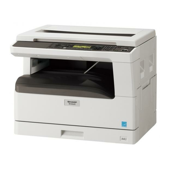
External Appearance
Identifies external parts and components of the machine.
Internal Components
Details internal components and their locations within the machine.
Operation Panel Section
Explains the function and display of the machine's operation panel.
Motors, Solenoids, and Clutches
Lists and describes the function of motors, solenoids, and clutches.
Sensors and Switches
Details the various sensors and switches and their functions.
PWB Units
Identifies the different Printed Wiring Board (PWB) units and their functions.
Cross-Sectional View
Illustrates the internal structure with a cross-sectional view.
Adjustments and Simulations
Adjustment Item List
Lists all adjustable items and their corresponding procedures or SIM numbers.
Copier Adjustment Procedures
Details specific copier adjustments, such as doctor gap and pole position.
Entering Simulation Mode
Procedure for accessing the machine's simulation modes.
List of Simulations
Comprehensive list of available simulations with main and sub codes.
Troubleshooting and Maintenance
Trouble Code List
Provides a quick reference for trouble codes by main and sub codes.
Details of Trouble Codes
Explains causes and remedies for specific trouble codes.
Maintenance Table
Outlines maintenance intervals and actions for various machine parts.
Maintenance Display System
Explains how to access and interpret maintenance information on the display.
Consumable Replacement Notes
Provides important notes regarding the handling of toner and developer cartridges.
Disassembly and Assembly Procedures
High Voltage and Duplex Transport Sections
Details the disassembly and assembly of high voltage and duplex transport sections.
Optical Section Disassembly
Provides instructions for disassembling and assembling the optical unit.
Fusing Section Components
Covers the disassembly and assembly of the fusing unit components.
Paper Exit Section
Details the disassembly and assembly of the paper exit unit and its parts.
MCU and NIC Components
Explains the disassembly procedures for the MCU and NIC.
Optical Frame Unit Installation
Covers the installation of the optical frame unit.
LSU Unit Handling
Instructions for handling the LSU unit, including notes on replacement.
Paper Feed and Transport Sections
Details the disassembly and assembly of paper feed and transport mechanisms.
Bypass Tray Section
Covers the disassembly and assembly of the bypass tray components.
Power Section Disassembly
Explains the disassembly of the power supply unit and switch.
Developing Section Components
Details the disassembly of the developing box, doctor, and MG roller.
Process Section Components
Covers the disassembly and handling of the drum unit and cleaning blade.
Other Component Disassembly
Details disassembly for various other components like PWBs and sensors.
Operational Descriptions
Paper Feed Operation
Describes the operational sequence of the paper feed system.
Firmware Update Procedures
Firmware Update Preparation
Lists necessary files and procedures for preparing the firmware update.
Firmware Download Procedure
Steps for performing the firmware download from PC to machine.
Maintenance Tool Installation
Guides on installing the maintenance tool driver on Windows.
Network Firmware Update Procedures
Specific steps for downloading firmware to N/N models via network.
Electrical System Diagrams
Electrical Block Diagram
Presents the overall block diagram of the machine's electrical system.
Actual Wiring Diagrams
Detailed wiring diagrams illustrating electrical connections between components.
Need help?
Do you have a question about the AR-5620S and is the answer not in the manual?
Questions and answers