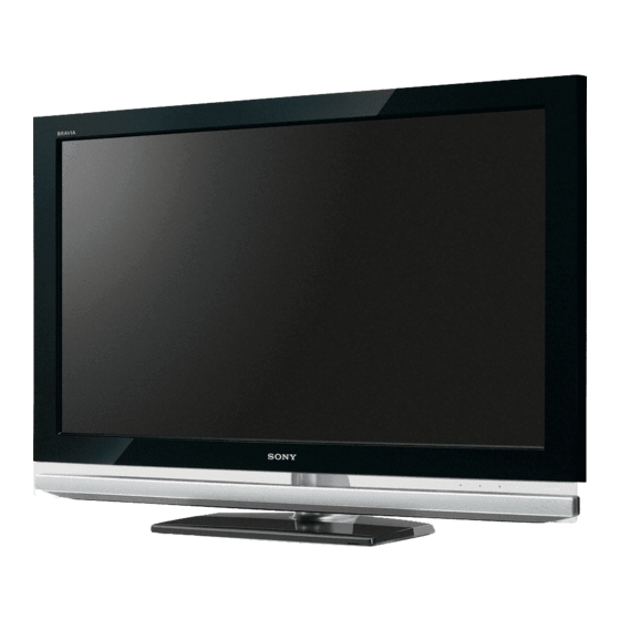
Sony BRAVIA KDL-52Z4500 Service Manual
Lcd digital colour tv
Hide thumbs
Also See for BRAVIA KDL-52Z4500:
- Operating instructions manual (56 pages) ,
- Brochure (2 pages) ,
- Operating instructions manual (59 pages)
Table of Contents
Advertisement
Advertisement
Table of Contents

Summarization of Contents
Specifications
PC Input Signal Reference (RGB)
Details PC input signal resolutions, frequencies, and standards for RGB connection.
PC Input Signal Reference (HDMI)
Lists supported PC input signal resolutions, frequencies, and standards for HDMI connection.
Warnings and Cautions
General Service Safety Warnings
Outlines general cautions for service personnel and risks of electric shock and component replacement.
LCD Panel Handling Precautions
Specific instructions for safely handling and repairing the LCD panel to prevent damage or injury.
Safety Check-Out
AC Leakage Test Procedure
Describes how to perform AC leakage tests on exposed metal parts to ensure safety.
Grounding Verification Method
Explains how to find and verify a reliable earth ground connection for safety tests.
Self Diagnosis Function
Diagnostic Test Indicators
Lists STANDBY LED flash counts and their corresponding diagnostic item descriptions for error identification.
Standby Light Flash Count Display
Illustrates the visual pattern of STANDBY LED flashes for self-diagnosis.
Stopping the Standby Flash
Instructions on how to turn off the flashing STANDBY LED after troubleshooting.
Self-Diagnostic Screen Display
Details how to access and view error history and diagnostic results on the screen.
Clearing Diagnostic Results
Procedures for resetting error counts and panel operation time displays to zero.
Quitting Self-Diagnostic Mode
Steps to exit the self-diagnostic screen and return to normal operation.
Troubleshooting
Triage Chart
A chart to help identify potential faulty components based on symptoms and LED blink patterns.
General Troubleshooting Flow Chart
A high-level flowchart guiding the user through initial troubleshooting steps.
No Power Troubleshooting
A flowchart specifically for diagnosing and resolving "no power" issues.
Self Diagnosis Error Code Overview
Provides a summary of STANDBY LED blink codes and their associated diagnostic items.
Self Diagnosis Flow Chart C
A detailed flowchart for self-diagnosis error identification based on LED blinks.
DC_DET Error (RED 2 Blinks)
Details the meaning and cause of the DC_DET error indicated by 2 LED blinks.
Backlight Error (RED 6 Blinks)
Details the meaning and cause of the Backlight error indicated by 6 LED blinks.
Temperature Error (RED 7 Blinks)
Details the meaning and cause of the Temperature error indicated by 7 LED blinks.
Audio Error (RED 8 Blinks)
Details the meaning and cause of the Audio error indicated by 8 LED blinks.
HFR Error (RED 9 Blinks)
Details the meaning and cause of the HFR error indicated by 9 LED blinks.
DEF Error (RED 10 Blinks)
Details the meaning and cause of the DEF error indicated by 10 LED blinks.
NVM Error (RED 11 Blinks)
Details the meaning and cause of the NVM error indicated by 11 LED blinks.
I2C Error (RED 12 Blinks)
Details the meaning and cause of the I2C error indicated by 12 LED blinks.
Balancer Error (RED 13 Blinks)
Details the meaning and cause of the Balancer error indicated by 13 LED blinks.
HDMI Error (RED 14 Blinks)
Details the meaning and cause of the HDMI error indicated by 14 LED blinks.
Tuner Error (RED 15 Blinks)
Details the meaning and cause of the Tuner error indicated by 15 LED blinks.
I2C-CH1 Error (RED 16 Blinks)
Details the meaning and cause of the I2C-CH1 error indicated by 16 LED blinks.
I2C-CH0 Error (RED 17 Blinks)
Details the meaning and cause of the I2C-CH0 error indicated by 17 LED blinks.
Digital Modulator Error (RED 18 Blinks)
Details the meaning and cause of the Digital Modulator error indicated by 18 LED blinks.
USB Error (RED 19 Blinks)
Details the meaning and cause of the USB error indicated by 19 LED blinks.
VCTP Error (RED 21 Blinks)
Details the meaning and cause of the VCTP error indicated by 21 LED blinks.
Audio Problem Diagnosis
A flowchart for troubleshooting audio-related issues.
Video Problem Diagnosis
A flowchart for troubleshooting video-related issues.
Spare Parts List
Spare Parts List for KDL-40Z4500
Lists part numbers and descriptions for the KDL-40Z4500 model.
Spare Parts List for KDL-46Z4500
Lists part numbers and descriptions for the KDL-46Z4500 model.
Spare Parts List for KDL-52Z4500
Lists part numbers and descriptions for the KDL-52Z4500 model.
Packing Materials
Packing Materials for KDL-40Z4500
Details the packing materials and their reference numbers for the KDL-40Z4500.
Packing Materials for KDL-46Z4500
Details the packing materials and their reference numbers for the KDL-46Z4500.
Packing Materials for KDL-52Z4500
Details the packing materials and their reference numbers for the KDL-52Z4500.


Need help?
Do you have a question about the BRAVIA KDL-52Z4500 and is the answer not in the manual?
Questions and answers