Table of Contents
Advertisement
SERVICE MANUAL
TECHNICAL INFORMATION
FOR SERVICE PERSONNEL ONLY
TYPE
MODEL
POWER SOURCE
TOTAL INPUT
TOTAL AMPERES
COOLING
CAPACITY
TOTAL INPUT
TOTAL AMPERES
HEATING
CAPACITY
DIMENSIONS
(mm)
NET WEIGHT
SPECIFICATIONS AND PARTS ARE SUBJECT TO CHANGE FOR IMPROVEMENT
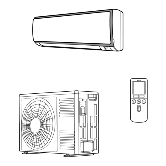
ROOM AIR CONDITIONER
FEBRUARY 2008 Hitachi Household Appliances(Wuhu) Co.,Ltd.
RAS-18FH6
RAS-25FH6
RAC-18YH6
RAC-25YH6
RAS-18FH6
1 PHASE, 50 Hz, 220-230V
(W)
550 (155 ~ 1,010)
(A)
2.95-2.81
(kW)
2.00 (0.90 ~ 2.50)
(B.T.U./h)
6,820 (3,070 ~ 8,530)
(W)
580 (115 ~ 970)
(A)
2.93-2.81
(kW)
2.50 (0.90 ~ 3.20)
(B.T.U./h)
8,530 (3,070 ~ 10,920)
W
780
H
280
D
220
(kg)
9.5
INDOOR UNIT + OUTDOOR UNIT
NO. 0024E
AW
RAS-18FH6 RAC-18YH6
RAS-25FH6 RAC-25YH6
REFER TO THE FOUNDATION MANUAL
SPECIFICATIONS ------------------------------------------------------------------- 4
HOW TO USE ----------------------------------------------------------------------- 5
CONSTRUCTION AND DIMENSIONAL DIAGRAM --------------------- 15
MAIN PARTS COMPONENT --------------------------------------------------- 17
WIRING DIAGRAM ---------------------------------------------------------------- 19
CIRCUIT DIAGRAM --------------------------------------------------------------- 20
BLOCK DIAGRAM ----------------------------------------------------------------- 22
BASIC MODE ----------------------------------------------------------------------- 23
REFRIGERATING CYCLE DIAGRAM --------------------------------------
DESCRIPTION OF MAIN CIRCUIT OPERATION ----------------------- 30
SERVICE CALL Q & A ---------------------------------------------------------- 60
TROUBLE SHOOTING ----------------------------------------------------------- 63
PARTS LIST AND DIAGRAM -------------------------------------------------- 90
DC INVERTER (WALL TYPE)
INDOOR UNIT
RAC-18YH6
RAS-25FH6
1 PHASE, 50 Hz, 220-230V
8,530 (3,070 ~ 10,580)
11,600 (3,070 ~ 15,010)
700 (+68)
780
505
280
258 (+48)
220
27
9.5
CONTENTS
--------------------------------------
OUTDOOR UNIT
RAC-25YH6
700 (155 ~ 1,290)
3.75-3.59
2.50 (0.90 ~ 3.10)
880 (115 ~ 1,250)
4.45-4.26
3.40 (0.90 ~ 4.40)
700 (+68)
505
258 (+48)
27
After installation
- 29
88
Advertisement
Table of Contents

Related Manuals for Hitachi RAS-25FH6


Summarization of Contents
Safety During Repair Work
General Safety Guidelines
Guidelines for safe disassembly, repair, and handling of parts.
Electrical Safety Checks
Checks for grounding, insulation resistance, and inflammable materials.
Semiconductor Handling Standards
Scope and Handling Procedures
Standards for handling semiconductor parts and preventing damage.
Operational Cautions
General and Temperature Limit Precautions
Cautions on operation noise, thunderstorms, power failure recovery, and temp limits.
Safety Precautions
Installation and Operation Safety
Precautions for installation, operation, and general safety warnings.
Unit Component Identification
Indoor/Outdoor Parts and Indicators
Identification of key parts for indoor and outdoor units and indicator functions.
Remote Controller Functions
Overview, Buttons, and Advanced Modes
Description of remote controller, its buttons, and advanced functions like Auto Restart.
Operating Modes
Heating, Dehumidifying, and Defrosting
Detailed guides for heating, dehumidifying, and defrosting operations.
Operating Modes
Cooling and Fan Operations
Guides for cooling operation and fan-only air circulation.
Timer Setting Procedures
Setting Off-Timer, On-Timer, and Canceling Reservations
Instructions for setting various timer functions and canceling them.
Unit Adjustments and Maintenance
Sleep Timer, Air Deflectors, and Battery Replacement
Procedures for setting sleep timer, adjusting air deflectors, and replacing remote batteries.
Routine Maintenance
Filter, Panel, and Storage Care
Procedures for cleaning air filters, front panel, and maintenance for long-term storage.
System Information and Service Checks
Capabilities and Pre-Service Checks
Overview of unit capabilities, regular inspection points, and service call checks.
Dimensional Diagrams
Indoor Unit Dimensions
Detailed dimensions and construction diagram for the indoor unit.
Dimensional Diagrams
Outdoor Unit Dimensions
Detailed dimensions and construction diagram for the outdoor unit.
Key Component Specifications
Thermostat, Fan Motor, and Outdoor Components
Specifications for thermostat, fan motor, and main electric components of the outdoor unit.
Basic Operation Modes
Mode Selection and Control Logic
Explanation of basic modes, fan speed control, and operation judgments.
Detailed Cooling Operation
Operation Analysis and Parameters
Analysis of cooling operation timing, parameters, and judgment criteria.
Specialized Operation Modes
Sleep, Defrost, and Dehumidifying
Details on sleep operation, defrosting, and dehumidifying modes.
Detailed Heating Operation
Operation Analysis and Parameters
Analysis of heating operation timing, parameters, and notes.
Advanced Heating and Defrosting
Reversing Valve Defrosting and Heating Sleep
Explanation of reversing valve defrosting and heating sleep operations.
Main Circuit Operation
Reset Circuit Functionality
Explanation of the reset circuit's function and operation.
Receiver and Buzzer Circuits
Description of the receiver and buzzer circuits.
Auto Sweep Motor Circuit
Explanation of the auto sweep motor drive circuit.
Initial Setting and Power Supply Circuits
Details on initial setting and power supply circuits.
Fan Motor Drive Circuit
Explanation of the fan motor drive circuit.
Power Circuitry
Circuit Overview and Components
Description of the power circuit, including main parts and waveform analysis.
Power Circuit Component Functions
Explanation of the functions of various components within the power circuit.
Inter-Unit Communication
Interface Circuit Overview
Description of the interface circuit for indoor/outdoor unit communication.
Interface Circuit Diagram
Diagram illustrating the indoor/outdoor interface circuit.
Communication Waveforms
Voltage waveforms for indoor/outdoor microcomputer communications.
Communication Format Diagram
Diagram showing the serial communication format during normal operations.
Serial Communication Data Formats
Tables detailing outdoor and indoor message formats for serial communication.
Intelligent Power Module (IPM) Circuit
IPM Circuit Overview
Overview of the IPM circuit and its internal diagram.
IPM Switching Order and Waveforms
Explanation of IPM switching order and voltage waveforms.
IPM Power Module Circuit and Diagnosis
IPM power module circuit diagram and diagnosis for defects.
Drive Circuitry
Drive Circuit Overview
Explanation of the inverter drive device and drive circuit within IPM.
Drive Signal Waveforms
Drive signal waveforms for low and high speed operations.
PWB Power Circuits
PWB Power Circuit Diagram
Diagram of the power circuit for the Printed Wiring Board (PWB).
PWB Power Circuit Voltage Specs and Troubleshooting
Voltage specifications and troubleshooting for PWB power circuit failures.
Microcomputer Peripheral Circuits
Peripheral Circuit Overview and Function
Overview of microcomputer peripheral circuits and their basic operations.
Peak Current Cutoff Circuit Analysis
Analysis of the peak current cutoff circuit and its waveforms.
Overload Control Circuit (OVL)
Explanation of the overload control circuit for compressor protection.
OVL Control Circuit Details (IS OVL, ID OVL)
Detailed explanation of IS OVL and ID OVL control circuits.
Start Current Control
Explanation of the software control for maintaining constant compressor start current.
Reset Circuit Functionality
Explanation of the reset circuit's role in initializing the microcomputer.
Temperature Detection Circuits
Description of circuits for detecting over-heat, defrost, and outdoor temperatures.
Reversing Valve Control Circuit
Explanation of the reversing valve control circuit and its operation modes.
Electric Expansion Valve Control
Explanation of the electric expansion valve control circuit and its logic waveforms.
Outdoor DC Fan Motor Control
Explanation of the DC fan motor control circuit and failure detection.
DC Fan Motor References and Cautions
References and cautions related to DC fan motor operation and potential issues.
Service Call Q&A
Cooling, Dehumidifying, and Heating Troubleshooting
Q&A for common issues in cooling, dehumidifying, and heating modes.
Other Operation and Remote Control Issues
Q&A for auto operation, timer, and remote control problems.
Miscellaneous Operation Issues
Q&A covering various other operational phenomena and user queries.
Indoor Unit Disassembly
Removing Electrical Parts and PWB
Procedures for removing electrical parts, control, and indicating PWB.
General Servicing Cautions
ICP and Connector Handling Cautions
Cautions regarding IC protector, connectors, probe connections, and power feeding.
Failure Diagnosis Functions
Self-Diagnosis Indication Overview
Explanation of self-diagnosis indication function for indoor/outdoor unit failures.
Self-Diagnosis Lighting Modes
Timer Lamp Blinking Troubleshooting
Troubleshooting based on timer lamp blinking patterns and reasons.
Detailed Self-Diagnosis Modes and LED Indicators
Detailed self-diagnosis modes, LED indicators, and their corresponding error causes.
Electrical Parts and Refrigeration Checking
Component Check Flowchart
Flowchart for checking indoor/outdoor unit electrical parts and refrigerating cycle.
Indoor Unit Power Troubleshooting
No Power Diagnosis Flowchart
Flowchart for diagnosing 'no power or no operation' issues in the indoor unit.
Indoor Unit Component Troubleshooting
Fan and Air Deflector Issues
Troubleshooting flowcharts for indoor fan not operating or air deflector not moving.
Control PWB Troubleshooting
Power Circuit Checks
Troubleshooting flowchart for control PWB power circuit issues.
Outdoor Unit Electrical Parts Troubleshooting
No Operation/Abnormal Operation Flowchart
Flowchart for checking outdoor unit electrical parts during no operation.
Fan Lock Error Troubleshooting
Troubleshooting steps for fan lock error indicated by LD301 blinking 12 times.
Refrigerating Cycle Troubleshooting
Gas Leak vs. Compressor Defect Diagnosis
Troubleshooting for no operation based on self-diagnosis and gas pressure.
Service Switch and Independent Operation
Service Switch and Independent Operation Procedures
Procedures for operating the outdoor unit using the service switch independently.
IPM Diagnosis Procedures
IPM Circuit Overview
Overview of the Intelligent Power Module (IPM) and its internal circuit.
IPM Multimeter Diagnosis
Procedure for diagnosing the power module using a multimeter.
Indoor Unit Disassembly and Reassembly
Removing Front Panel, Cover, and PWB
Steps for disassembling the indoor unit's front panel, cover, and PWB components.
Fan Motor and Outdoor Parts Disassembly
Disassembly procedures for the fan motor and outdoor unit electrical parts.
Indoor Unit Parts List and Diagram
Indoor Unit Parts Catalog
Detailed list of parts for the indoor unit with part numbers.
Outdoor Unit Parts Diagram
Outdoor Unit Parts Catalog
Detailed list of parts for the outdoor unit with part numbers.
Need help?
Do you have a question about the RAS-25FH6 and is the answer not in the manual?
Questions and answers