Advertisement
Quick Links
Download this manual
See also:
Instruction Manual
CD RECEIVER
KDC-MP4036U/MP435U/X491
KDC-W4537UA/W4537UAY
KDC-W4537UG/W4537UGY
KDC-W4737U/W4737UY
SERVICE MANUAL
Panel assy
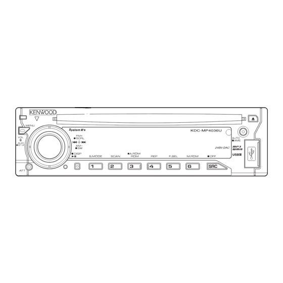
KDC-MP4036U (A64-4129-12)
Panel assy
KDC-W4537Uxx (A64-4127-12)
Panel assy
KDC-X491 (A64-4221-12)
Mounting hardware assy
(J21-9716-03)
* Antenna adaptor
* Screw set
(T90-0523-05)
(N99-1757-05)
* Depends on the model. Refer to the parts list.
KDC-MP4036U
KDC-W4537U
KDC-X491
* DC cord
* DC cord
(E30-6428-05)
(E30-6671-05)
Lever
* Plastic cabinet assy
(D10-4589-04) x2
(A02-2736-03)
This product complies with the
© 2007-4 PRINTED IN JA PAN
B53-0513-00 ( N ) 552
Panel assy
KDC-MP435U (A64-4126-12)
Panel assy
KDC-MP4737U/MP4737UY (A64-4175-12)
SPARE TDF PANEL
MAIN UNIT NAME
TDF PARTS No.
KDC-MP4036U
Y33-2720-64
KDC-MP435U
Y33-2720-61
KDC-W4537UA
Y33-2720-63
KDC-W4537UAY
Y33-2720-63
KDC-W4537UG
Y33-2720-63
KDC-W4537UGY
Y33-2720-63
KDC-W4737U
Y33-2720-62
KDC-W4737UY
Y33-2720-62
KDC-X491
Y33-2720-60
* Remote controller assy (RC-xxx)
(A70-xxxx-xx)
* Carrying case
(W01-xxxx-xx)
This product uses Lead Free solder.
RoHS
KDC-MP435U
KDC-W4737U
TDF NAME
TDF-MP4036U
TDF-MP74D
TDF-W4537U
TDF-W4537U
TDF-W4537U
TDF-W4537U
TDF-W4737U
TDF-W4737U
TDF-MP74DX
Battery
(Not supplied)
Escutcheon
(B07-3125-01)
directive for the European market.
Advertisement

Related Manuals for Kenwood KDC-X491


Summarization of Contents
Components Description
Electric Unit Components
Details and functions of electronic components within the electric unit, including ICs and transistors.
Switch Unit Components
Description of components specific to the switch unit, such as LEDs and sensors.
CD Player Unit Components
Description of components within the CD player unit, covering processors, drivers, and protection circuits.
Test Mode Operations
Entering and Clearing Test Mode
Procedures for entering and exiting the device's test mode.
Tuner Mode Special Displays
Information on special error indicators and switching modes within tuner operation.
CD Source Test Specifications
Details and procedures for testing CD source functionality, including track jumping.
Audio Adjustment Mode
Guide to adjusting audio settings like fader, bass, treble, and EQ within test mode.
DC Offset Error Detection
Purpose and Processing After Detection
Explains the function of DC offset error detection and system response upon detection.
Cancel Conditions and Test Mode Notes
Details on how to cancel DC offset errors and notes on test mode behavior.
Exploded Views
CD Mechanism Exploded View
Diagram showing the assembly of the CD mechanism components.
Unit Components Exploded View
Diagram illustrating the assembly of the main unit components.
Parts List
Switch Unit Parts
List of part numbers and descriptions for the switch unit.
Electric Unit Parts
Comprehensive list of part numbers and descriptions for the electric unit.
Mechanism Assembly Parts List
List of part numbers and descriptions for the CD mechanism assembly.
Component Identification
Capacitor Identification
Guides for identifying capacitor types, values, ratings, and dimensions.
Resistor Identification
Guides for identifying resistor types, values, and wattage.
Specifications
FM Tuner Specifications
Detailed performance specifications for the FM tuner section.
AM Tuner Specifications
Detailed performance specifications for the AM tuner section.
CD Player Specifications
Technical specifications related to the CD player functionality.
Audio Specifications
Details on output power, impedance, and frequency response of the audio section.
Need help?
Do you have a question about the KDC-X491 and is the answer not in the manual?
Questions and answers