Table of Contents
Advertisement
Service
Manual
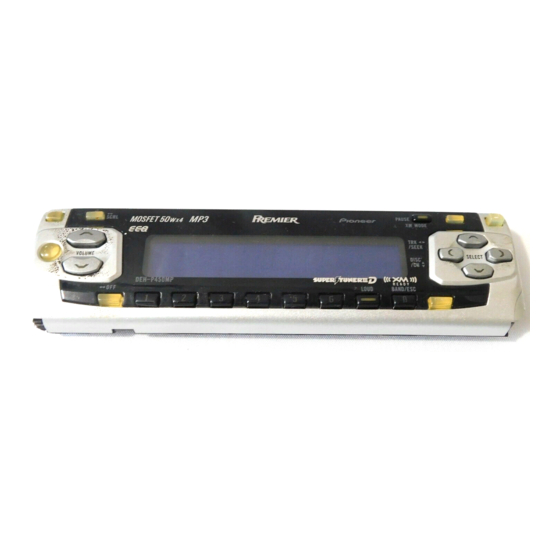
MULTI-CD CONTROL HIGH POWER CD/MP3 PLAYER WITH FM/AM TUNER
DEH-P450MP
DEH-P4500MP
DEH-P3550MP
- This service manual should be used together with the following manual(s):
Model No.
Order No.
CX-3057
CRT3026
For details, refer to "Important symbols for good services".
PIONEER CORPORATION
PIONEER ELECTRONICS (USA) INC.
PIONEER EUROPE NV
Haven 1087 Keetberglaan 1, 9120 Melsele, Belgium
PIONEER ELECTRONICS ASIACENTRE PTE.LTD. 253 Alexandra Road, #04-01, Singapore 159936
C PIONEER CORPORATION 2003
DEH-P450MP/XM/UC
Mech. Module Remarks
S10MP3
CD Mech. Module:Circuit Description, Mech.Description, Disassembly
4-1, Meguro 1-Chome, Meguro-ku, Tokyo 153-8654, Japan
P.O.Box 1760, Long Beach, CA 90801-1760 U.S.A.
XM/UC
XM/ES
K-ZZY. JAN. 2003 Printed in Japan
ORDER NO.
CRT3019
XM/UC
Advertisement
Table of Contents

Related Manuals for Pioneer DEH-3550MP


Summarization of Contents
Safety Information
Important Symbols for Good Services
Explains crucial symbols for service procedures, ensuring correct execution.
Specifications
General
Covers general electrical and physical specifications of the unit.
Audio
Specifies audio output power, impedance, and equalizer settings.
CD player
Technical details related to CD playback performance.
FM tuner
Specifications for FM radio reception.
AM tuner
Specifications for AM radio reception.
Exploded Views and Parts List
PACKING
Details on the packaging components for the unit.
EXTERIOR (DEH-P450MP, P4500MP)
Exploded view and parts list for the external components of specific models.
EXTERIOR (DEH-P3550MP)
Exploded view and parts list for the external components of the DEH-P3550MP model.
CD MECHANISM MODULE
Exploded view and parts list for the CD mechanism assembly.
Block Diagram and Schematic Diagram
BLOCK DIAGRAM
High-level overview of the unit's functional blocks and their interconnections.
OVERALL CONNECTION DIAGRAM(GUIDE PAGE)
Illustrates how major internal units are interconnected.
KEYBOARD UNIT
Detailed block diagram for the keyboard control unit.
PANEL UNIT
Detailed block diagram for the panel unit.
CD MECHANISM MODULE
Detailed block diagram of the CD mechanism's internal circuitry.
PCB Connection Diagram
TUNER AMP UNIT
PCB layout and connector map for the Tuner Amplifier unit.
PANEL UNIT
PCB layout and connector map for the Panel unit.
KEYBOARD UNIT
PCB layout and connector map for the Keyboard unit.
CD MECHANISM MODULE
PCB layout and connector map for the CD Mechanism module.
Adjustment
JIG CONNECTION DIAGRAM
Diagram showing how to connect test jigs for adjustment procedures.
CD ADJUSTMENT
Specific steps and cautions for adjusting the CD mechanism module.
CHECKING THE GRATING AFTER CHANGING THE PICKUP UNIT
Procedure to verify the pickup unit's grating angle after replacement.
ERROR MODE
Explains error codes and their potential causes for troubleshooting.
General Information
DIAGNOSIS
Methods for diagnosing unit malfunctions.
DISASSEMBLY
Step-by-step instructions for disassembling the unit.
CONNECTOR FUNCTION DESCRIPTION
Detailed pinout and function of external connectors.
Operations
Head unit
Description of the controls and functions on the main unit.
Remote control
Explanation of how to use the remote control for unit operation.
Playing a CD
Step-by-step guide on how to play a CD using the unit.
Fixing the Front Panel
Instructions for attaching and securing the front panel assembly.
Need help?
Do you have a question about the DEH-3550MP and is the answer not in the manual?
Questions and answers