Table of Contents
Advertisement
Audison measurement standards
(Power measures taken according to audison standard, 1998 edition)
- 12VDC and 13.8VDC;
- 1 kHz or crossover cut-off frequency;
- 0.3% THD @ nominal power; 1% THD @ continuous power;
- Tolerance: +10%; -5%;
- Continous power given by RMS Voltage measured on resistive load;
- The nominal power of the amplifier is measured upon a battery voltage of 12 Volts with
a 4 Ohm load and with all channels in function.
is a division of
62018 Potenza Picena (MC) Italy
Tel. 0733.870870 • Fax 0733.870880 • http://www.audison.com • e-mail: com@audison.com
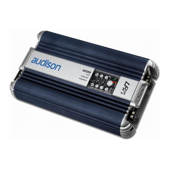
OWNER'S MANUAL
CAR POWER AMPLIFIERS
Advertisement
Table of Contents

Related Manuals for Audison LRx 2.500


Summarization of Contents
Introduction
Precautions
Safety measures for amplifier installation and usage.
Warning
Warning about battery positive cable contact with heat sink.
Cautions
Advice on connecting signal grounds and output grounds.
Installation
Audison Cable Products for Electric Connections
Recommended power supply and speaker cables with specifications.
Recommended Speakers Cables
Recommended speaker cable types and sizes.
Recommended Signal Cables
Recommended signal cable lengths for RCA extensions.
Amplifier Fixing
How to secure the amplifier using self-tapping screws.
Electric Connections
Wiring diagram for loudspeakers, accessories, and power supply.
Description
Logo Rotation
Instructions for rotating the amplifier logo plate.
In-Out Panel
Functions
Describes the purpose of different connectors on the panel.
Left/Right
Power outputs for left and right channels, and mono bridge connection.
PPS (Phantom Power Supply)
Power supply socket for external audio accessories.
Out
Preamplified outputs (PRE OUT) for sending signals to another amplifier.
In
Inputs (PRE IN) for connecting sources or crossovers.
Power Supply Panel
Remote In
Terminal to connect Remote cable for amplifier switching.
Remote Out
Terminals to repeat the switching on control for other devices.
Fuse
Strip fuse for amplifier general protection, replacement advice.
Power
Terminal blocks for amplifier power supply cable connection.
Controls Panel
Limit (Orange LED)
Indicates the Overload Limiter circuit is active.
ON (Green LED)
Indicates that the amplifier is powered on.
AMP: HI/LO-PASS (Pre Out: Lo/Hi-Pass)
Selects signal type (Lo-Pass or Hi-Pass) for amplifier stage.
Mode
Switches amplifier mode between Stereo and Mono (bridged).
Levels
Adjusts input sensitivity and output level.
F1
Sets Lo-Pass and Hi-Pass crossover point between 40 and 500 Hz.
Range: x1/x10
Selects frequency ranges for crossover point adjustment.
Hi-Pass
Activates or bypasses the Hi-PASS filter.
Lo-Pass
Activates or bypasses the LO-PASS filter.
Safety (Red LED)
Indicates amplifier protection circuits are active.
Technical Features
Size for Fixing
Dimensions and drilling information for amplifier mounting.
Power Supply
Electrical specifications including voltage, current, and power output.
Amplifier Stage
Performance metrics like distortion, bandwidth, and S/N ratio.
Filters/Inputs
Details on crossover filters and input configurations.
Other Functions
Information on remote connections and auxiliary power supply.
Configurations Table
Overview of different amplifier configuration settings.
Accessories
CLK2 - LRx Cooling Kit
Description and function of the optional cooling system.
Need help?
Do you have a question about the LRx 2.500 and is the answer not in the manual?
Questions and answers