Table of Contents
Advertisement
HCD-ZX80D/ZX100D
SERVICE MANUAL
Ver. 1.2 2007.08
HCD-ZX80D is the amplifier, disc player, tape deck
and tuner section in FST-ZX80D/LBT-ZX80D.
HCD-ZX100D is the amplifier, disc player, tape deck
and tuner section in FST-ZX100D/LBT-ZX100D.
This system incorporates Dolby* Digital, Dolby
Pro Logic (II) adaptive matrix surround decoder,
and the DTS** Digital Surround System.
* Manufactured under license from Dolby
Laboratories.
"Dolby", "Pro Logic", and the double-D
symbol are trademarks of Dolby
Laboratories.
**Manufactured under license from Digital
Theater Systems, Inc.
"DTS" and " DTS Digital Surround" are
registered trademarks of Digital Theater
Systems, Inc.
AUDIO POWER SPECIFICATION
(HCD-ZX80D USA model only)
POWER OUTPUT AND TOTAL HARMONIC
DISTORTION:
With 6-ohm loads, both channels driven, from
120 Hz 10 kHz; rates 160 watts per channel
minimum RMS power, with no more than 10% total
harmonic distortion from 250 milliwatts to rated output.
Continuous RMS power output (reference)
Front speaker:
200 W + 200 W
(6 ohms at 1 kHz, 10% THD)
Center speaker:
80 W
(16 ohms at 1 kHz, 10%
THD)
Surround speaker:
200 W + 200 W
(6 ohms at 1 kHz, 10% THD)
Amplifier section
HCD-ZX100D
The following are measured at AC 120, 127, 220,
240V 50/60 Hz
DIN power output (rated): 130 W + 130 W
(6 ohms at 1 kHz, DIN)
Continuous RMS power output (reference)
Sony Corporation
9-887-251-03
Personal Audio Division
2007H05-1
Published by Sony Techno Create Corporation
© 2007.08
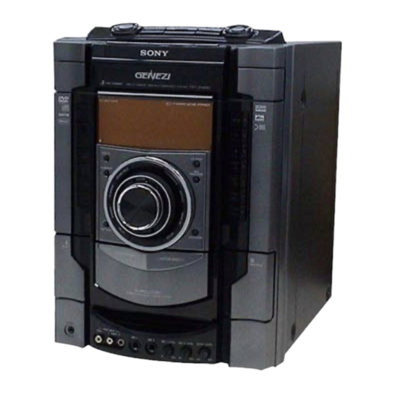
Photo: HCD-ZX80D
Model Name Using Similar Mechanism
DVD
DVD Mechanism Type
Section
Optical Pick-up Block Name
Tape deck
Model Name Using Similar Mechanism
Section
Tape Transport Mechanism Type
SPECIFICATIONS
Front speaker:
170 W + 170 W
(6 ohms at 1 kHz, 10% THD)
Center speaker:
80 W
(16 ohms at 1 kHz, 10%
THD)
Surround speaker:
170 W + 170 W
(6 ohms at 1 kHz, 10%
THD)
Subwoofer:
180 W (8 ohms at 100 Hz,
10% THD)
HCD-ZX80D
The following are measured at AC 120, 127, 220,
240V 50/60 Hz
DIN power output (rated):155 W + 155 W
(6 ohms at 1 kHz, DIN)
Continuous RMS power output (reference)
Front speaker:
200 W + 200 W
(6 ohms at 1 kHz, 10%
THD)
Center speaker:
80 W
(16 ohms at 1 kHz, 10%
THD)
Surround speaker:
200 W + 200 W
(6 ohms at 1 kHz, 10%
THD)
US Model
HCD-ZX80D
E Model
HCD-ZX80D/ZX100D
NEW
CDM74HF-DVBU101
KHM-310CAB or KHM-313CAB
NEW
CWN42RR603
Inputs
VIDEO INPUT (phono jacks):
VIDEO: 1 Vp-p, 75 ohms
AUDIO L/R: Voltage
250 mV, impedance 47
kilohms
TV/SAT AUDIO IN L/R (phono jacks):
Voltage 250 mV/450 mV,
impedance 47 kilohms
MIC 1 or 2 (phone jack): Sensitivity 1 mV,
impedance 10 kilohms
Outputs
AUDIO OUT (phono jacks):
Voltage 250 mV,
impedance 1 kilohm
VIDEO OUT (phono jack):
Max. output level 1 Vp-p,
unbalanced, Sync.
negative load impedance
75 ohms
COMPONENT VIDEO OUT:
Y: 1 Vp-p, 75 ohms
P
/C
: 0.7 Vp-p, 75 ohms
B
B
P
/C
: 0.7 Vp-p, 75 ohms
R
R
– Continued on next page –
DVD DECK RECEIVER
Advertisement
Table of Contents

Related Manuals for Sony HCD-ZX100D


Summarization of Contents
Servicing Notes and Precautions
Handling Optical Pick-Up Block
Precautions for handling the optical pick-up block and base unit to prevent damage.
Laser Diode Emission Check Safety
Safety guidelines for checking the laser diode emission from the optical pick-up block.
Unleaded Solder Handling
Characteristics and handling of unleaded solder for repairs.
General Information and Controls
Location of Controls
Identifies controls on the unit's front panel and remote control.
Setting the Clock
Instructions for setting the system's clock time.
Disassembly Procedures
Disassembly Flow Chart
Provides a flow diagram for disassembling the set in order.
Case Removal Procedure
Details the procedure for removing the outer case of the unit.
Escutcheon Top Block Removal
Instructions for disassembling the escutcheon or top front panel assembly.
Loading Panel Removal
Procedure for removing the disc loading panel assembly.
Tuner (FM/AM) (TM10SE) Removal
Steps for removing the FM/AM tuner module (TM10SE).
DVD Mechanism Deck Block Removal
Instructions for removing the entire DVD mechanism deck assembly.
Front Panel Block Removal
Details on how to remove the front panel assembly.
Back Panel Block Removal
Procedure for removing the back panel assembly.
Main Board Block Removal
Steps for removing the main board assembly.
Main Board Removal
Instructions for removing the main board itself.
Cover (CDM) Removal
Procedure for removing the cover related to the CDM unit.
Driver Board, SW Board Removal
Details on disassembling the driver and SW boards.
Optical Pick-Up Block Removal
Procedure for removing the optical pick-up block.
Sensor Board Removal
Steps for removing the sensor board.
Motor (TB) Board Removal
Procedure for removing the motor (TB) board.
Motor (LD) Board Removal
Steps for removing the motor (LD) board.
Test Modes and Diagnostics
Panel Test Mode
Checks panel indicators, controls, and version information.
Common Test Mode
Checks amplifier and tape operations, including GEQ and volume controls.
Cold Reset Procedure
Resets system data and settings to initial factory conditions.
VACS On/Off Mode
Controls the Variable Attenuation Control System feature.
Mechanical Adjustments Precautions
Precautions regarding cleaning, demagnetizing, and tool usage for adjustments.
Torque Measurement Specifications
Provides torque specifications for various mechanical parts.
Electrical Adjustments Overview
Procedures for adjusting electrical parameters like RFMON level.
Diagrams Overview
Provides block diagrams for various sections like RF Servo, MIC, Tuner, Audio, AMP.
Exploded Views and Parts Lists
Case and Escutcheon Top Exploded View
Exploded view of the case and escutcheon top assembly with parts.
Panel Board Section Exploded View
Exploded view of the panel board section with its parts.
Tape Mecha Deck Section Exploded View
Exploded view of the tape mechanism deck section with parts.
Back Panel Section Exploded View
Exploded view of the back panel section and associated boards.
DMB15/Karaoke/Video Boards Section
Exploded view showing the location of DMB15, Karaoke, and Video boards.
Main/PA/Surround Boards Section
Exploded view showing the location of Main, PA, and Surround boards.
Power Transformer Section
Exploded view of the power transformer and associated trans boards.
DVD Mechanism Deck Section-1
Exploded view of the DVD mechanism deck section, part 1.
DVD Mechanism Deck Section-2
Exploded view of the DVD mechanism deck section, part 2.
Electrical Parts List
Comprehensive list of electrical components for various boards.
DMB15 Board Parts List
List of electrical components for the DMB15 board.
Effectors Board Parts List
List of electrical components for the effector board.
Panel Board Parts List
List of electrical components for the panel board.
Need help?
Do you have a question about the HCD-ZX100D and is the answer not in the manual?
Questions and answers