Table of Contents
Advertisement
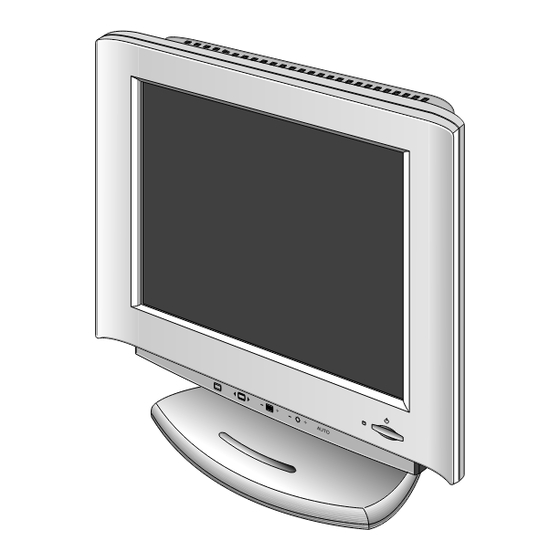
COLOR MONITOR
SERVICE MANUAL
CHASSIS NO. : CL-06
MODEL:
StudioWorks 570LE / 570LS, LB570BZ
ID LABEL : LB570D-EA / LB570E-EA / LB570D-EN
CAUTION
BEFORE SERVICING THE UNIT,
READ THE SAFETY PRECAUTIONS IN THIS MANUAL.
Website:http://biz.LGservice.com
E-mail:http://www.LGEservice.com/techsup.html
Same looking with New Chassis
Issue Date: JULY 2000
Advertisement
Table of Contents

Related Manuals for LG StudioWorks 570LS


Summarization of Contents
Precautions
Safety Component Precautions
Critical safety components marked on diagrams require specific replacement parts.
LCD Module Handling Precautions
Handle LCD module with care; avoid pressing, scratching, or exposure to extreme conditions.
Electrical Shock Warning
Disconnect AC adapter before servicing; high voltage present at inverter circuit.
Backlight Brightness Caution
Dimming backlight may require replacement of backlight unit.
Operating Instructions
Front View and Control Panel
Identifies front panel buttons: Power, OSD, Selection, Adjustment, and Brightness controls.
Rear View Controls
Identifies rear panel ports: ID Label, D-Sub, Power Input Socket.
On-Screen Display (OSD) Control
Guides users through OSD menu navigation for image adjustments and settings.
Disassembly Procedures
Tilt/Swivel and Back Cover Removal
Instructions for removing the tilt/swivel stand and the back cover.
Shield Removal Steps
Steps to remove top and inverter shields, including screw and latch release.
PCB Assembly Removal
Procedure for removing inverter, power, control, and main PCBs.
Backlight and LCD Module Removal
Steps for removing the backlight assembly and the LCD module.
Block Diagrams
System Block Diagram
High-level overview of main components: Power Supply, Main Logic PCB, Control PCB, LCD Module.
Model-Specific Block Diagrams
Detailed block diagrams for LB570D (570LE) and LB570E (570LS) models.
Block Diagram Descriptions
LB570D Block Diagram Details
Explanation of circuits: Video Amp, Macronix, Memory, Panel-Link, System Controller, DC/DC Converter.
LB570E Block Diagram Details
Explanation of circuits: Video Amp, Macronix, Memory, System Controller, DC/DC Converter.
Adjustment Procedures
Factory Preset Mode Adjustment
Procedure for factory preset adjustments using PC, EEPROM, and signal generator.
White Balance and DDC Data Adjustment
Steps for white balance calibration and DDC data write procedure.
Troubleshooting Guide
No Power Troubleshooting
Flowchart for diagnosing and resolving 'No Power' issues.
No Raster Troubleshooting (OSD Issues)
Flowcharts for diagnosing 'No Raster' problems related to OSD, Inverter, MX88L284, TDA8752BH.
Printed Circuit Boards
Main Board Layouts
Component and solder side layouts of the main printed circuit board.
Control Board Layouts
Component and solder side layouts of the control printed circuit board.
Exploded View
Exploded View Parts List
List of all parts with reference numbers, part numbers, descriptions, and quantities.
Pin Configurations
MX88L284 Pin Configuration
Pinout details for the MX88L284 video processor IC.
TDA8752 Pin Description
Pinout details and descriptions for the TDA8752 ADC IC.
Sil100 Pin Configuration
Pinout details for the Sil100 panel link transmitter IC.
L4973 Series Pin Functions
Pin functions for L4973V3/V5/D3/D5 switching regulators.
Schematic Diagrams
TDA8752 Schematic
Schematic for the TDA8752 pre-amplifier, PLL, and ADC circuit.
Video Process Schematic
Schematic diagram for the video processing section.
Panel-Link Schematic
Schematic diagram for the panel link interface.
Memory Schematic
Schematic diagram for the SDRAM memory circuits.
MICOM Schematic
Schematic diagram for the microcontroller (MICOM) circuit.
Power Generation Schematic
Schematic diagram for the power supply and voltage regulation circuits.
Connectors & Jacks Schematic
Schematic diagram for external connectors and internal jacks.
Need help?
Do you have a question about the StudioWorks 570LS and is the answer not in the manual?
Questions and answers