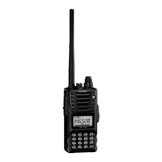
Yaesu VX-170 - APRS Manual
Vhf fm transceiver
Hide thumbs
Also See for VX-170 - APRS:
- Specifications (2 pages) ,
- Operating manual (88 pages) ,
- Technical supplement (32 pages)
Table of Contents
Advertisement
Quick Links
VHF FM TRANSCEIVER
VX-170
O
M
PERATING
ANUAL
VERTEX STANDARD CO., LTD.
4-8-8 Nakameguro, Meguro-Ku, Tokyo 153-8644, Japan
VERTEX STANDARD
US Headquarters
10900 Walker Street, Cypress, CA 90630, U.S.A.
YAESU UK LTD.
Unit 12, Sun Valley Business Park, Winnall Close
Winchester, Hampshire, SO23 0LB, U.K.
VERTEX STANDARD HK LTD.
Unit 5, 20/F., Seaview Centre, 139-141 Hoi Bun Road,
Kwun Tong, Kowloon, Hong Kong
VERTEX STANDARD ( AUSTRALIA ) PTY., LTD.
Normanby Business Park, Unit 14/45 Normanby Road
Notting Hill 3168, Victoria, Australia
Advertisement
Table of Contents

Related Manuals for Yaesu VX-170 - APRS


Summary of Contents for Yaesu VX-170 - APRS
- Page 1 4-8-8 Nakameguro, Meguro-Ku, Tokyo 153-8644, Japan VERTEX STANDARD US Headquarters 10900 Walker Street, Cypress, CA 90630, U.S.A. YAESU UK LTD. Unit 12, Sun Valley Business Park, Winnall Close Winchester, Hampshire, SO23 0LB, U.K. VERTEX STANDARD HK LTD. Unit 5, 20/F., Seaview Centre, 139-141 Hoi Bun Road, Kwun Tong, Kowloon, Hong Kong VERTEX STANDARD ( AUSTRALIA ) PTY., LTD.
-
Page 2: Table Of Contents
Contents General Description ......... 1 Scanning ............36 Accessories & Options ........2 VFO Scanning ..........37 Controls & Connections ........3 Manual VFO Scan ........37 Top & Front Panel .......... 3 Programmed VFO Scan ......37 LCD ..............4 Memory Scanning ........ -
Page 3: General Description
ENERAL ESCRIPTION The VX-170 is a compact, high-performance FM hand-held providing up to five watts of RF power and wealth of convenient features for the 2-meter amateur band. New and exciting features of the VX-170 are Enhanced Paging and Code Squelch (EPCS), that allows you to page a particular station and only receive calls from that station, if desired;... -
Page 4: Accessories & Options
& O CCESSORIES PTIONS UPPLIED CCESSORIES FNB-83 7.2 V, 1,400 mAh Rechargeable Nickel-Metal Hydride Battery Pack NC-88B Overnight Battery Charger (10-Hour) YHA-68 Antenna Quick Draw Belt Clip Operating Manual Warranty Card VAILABLE PTIONS FNB-83 7.2 V, 1,400 mAh Rechargeable Nickel-Metal Hydride Battery Pack NC-88B/C/U Overnight Battery Charger (10-Hour) VAC-370... -
Page 5: Controls & Connections
& C ONNECTORS ( T ONTROLS & F RONT ANELS Antenna Jack Connect the supplied rubber flex antenna (or an- other antenna presenting a 50-Ohm impedance) here. MIC/SP Jack This four-conductor miniature jack provides con- nection points for microphone audio, earphone audio, PTT, and ground. - Page 6 & C ONNECTORS ( LCD ) ONTROLS Memory Channel Number Skip Memory Channel or Repeater Shift Direction Preferential Memory Channel CTCSS/DSC Operation Internet Connection Priority Channel Feature Active Memory Bank Active Bell Alarm Active Operating Frequency Secondary Keypad Active Battery Indicator Low TX Power Selected S- &...
-
Page 7: Side Panel
& C ONNECTORS ( S ONTROLS ANEL PTT (Push To Talk) Switch Press this switch to transmit, and release it (to receive) after your transmission is com- pleted. MONI Switch Pressing this switch disables the noise squelching action, allowing you to hear very weak signals near the background noise level temporarily. -
Page 8: Keypad Functions
& C ONNECTORS ( K ONTROLS EYPAD UNCTIONS Primary Function Frequency entry digit “1.” Frequency entry digit “2.” RESS Secondary Function Activates the CTCSS or Selects the CTCSS tone or [ F ] + K DCS Operation. DCS code number. RESS Third Function Toggles the “Weather”... - Page 9 & C ONNECTORS ( K ONTROLS EYPAD UNCTIONS Increases the VFO frequency by Primary Function Frequency entry digit “3.” one step or moves the memory RESS channel to the next-highest channel. Secondary Function Selects the desired transmit power Tunes the VFO frequency [ F ] + K output level.
-
Page 10: Installation Of Accessories
NSTALLATION OF CCESSORIES NTENNA NSTALLATION The supplied antenna provides good results over the entire frequency range of the transceiver. However, for enhanced reception on certain non-Amateur frequencies, you may wish to connect an antenna designed specifically for that frequency range, as the supplied antenna is necessarily a compromise outside the Amateur band, and cannot be expected to provide high performance at all frequencies. -
Page 11: Battery Charging
NSTALLATION OF CCESSORIES ATTERY HARGING If the battery has never been used, or its charge is depleted, it may be charged by connect- ing the NC-88 Overnight Battery Charger, as shown in the illustration, to the EXT DC jack. If only 12 ~ 16 Volt DC power is available, the optional E-DC-5B DC Cable (with its cigarette lighter plug) or E-DC-6 DC Cable (plug and wire only) may also be used for charging the battery. -
Page 12: Belt Clip Installation
NSTALLATION OF CCESSORIES NSTALLATION Connect the hanger to the rear of the VX-170, with the notch pointing directly up, using the supplied screw (Figure 1). Use only the screw included with the clip to mount the clip to the back of the VX-170. Clip the Quick-Draw Belt Clip onto your belt (Figure 2). -
Page 13: Interface Of Packet Tncs
The VX-170 may be used for Packet operation, using the optional CT-91 Microphone Adapter (available from your Yaesu dealer) for easy interconnection to commonly-avail- able connectors wired to your TNC. You may also build your own cable, using a four- conductor miniature phone plug, per the diagram below. -
Page 14: Operation
PERATION Hi! I’m R. F. Radio, and I’ll be helping you along as you learn the many features of the VX-170. I know you’re anxious to get on the air, but I encour- age you to read the “Operation” section of this manual as thoroughly as possible, so you’ll get the most out of this fantastic new transceiver. -
Page 15: Squelch Adjustment
PERATION QUELCH DJUSTMENT To set the squelch, press the [ F] key, followed by the MONI switch just below the PTT switch on the left side of the transceiver. Now rotate the DIAL (outer knob) to find the lowest setting (“ LVL 1 LVL 1 LVL 1... - Page 16 PERATION REQUENCY AVIGATION 2 ) Direct Keypad Frequency Entry The desired operating frequency may be entered directly from the keypad. The first “1” in the frequency does not need to be entered, as it is “assumed” by the microprocessor. To enter a frequency directly, just key in the 10 MHz, 1 MHz, and the kHz digits. Examples: To enter 146.560 MHz, press [ 4 ] [ 6 ] [ 5 ]...
-
Page 17: Transmission
PERATION RANSMISSION Once you have set up an appropriate frequency inside the 144 MHz Amateur band on which the VX-170 can transmit, you’re ready to go on the air! These are the most basic steps; more advanced aspects of transmitter operation will be discussed later. To transmit, press the PTT switch, and speak into the front panel microphone (located in the lower left-hand corner of the speaker grille) in a normal voice level. -
Page 18: Advanced Operation
DVANCED PERATION Now that you’re mastered the basics of VX-170 operation, let’s learn more about some of the really neat features. EYBOARD OCKING In order to prevent accidental frequency change or inadvertent transmission, various as- pects of the VX-170’s DIAL and keypad may be locked out. The possible lockout combi- nations are: LK KEY LK KEY... -
Page 19: Keypad/Lcd Illumination
DVANCED PERATION /LCD I EYPAD LLUMINATION Your VX-170 includes a reddish illumination lamp which aids in nighttime operation. The reddish illumination yields clear viewing of the display in a dark environment, with mini- mal degradation of your night vision. Three options for activating the lamp are provided: Mode: Illuminates the Keypad/LCD lamp for five seconds when you rotate the DIAL knob or press the keypad or any switch (except PTT switch). -
Page 20: Rf Squelch
DVANCED PERATION RF S QUELCH A special RF Squelch feature is provided on this radio. This feature allows you to set the squelch so that only signals exceeding a certain S-meter level will open the squelch. To set up the RF squelch circuit for operation, use the following procedure: 1. -
Page 21: Repeater Operation
EPEATER PERATION Repeater stations, usually located on mountaintops or other high locations, provide a dra- matic extension of the communication range for low-powered hand-held or mobile trans- ceivers. The VX-170 includes a number of features which make repeater operation simple and enjoyable. -
Page 22: Manual Repeater Shift Activation
EPEATER PERATION ANUAL EPEATER HIFT CTIVATION If the ARS feature has been disabled, or if you need to set a repeater shift direction other than that established by the ARS, you may set the direction of the repeater shift manually. To do this: 1. -
Page 23: Vfo Split Mode
EPEATER PERATION ANUAL EPEATER HIFT CTIVATION Checking the Repeater Uplink (Input) Frequency It often is helpful to be able to check the uplink (input) frequency of a repeater, to see if the calling station is within direct (“Simplex”) range. To do this, just press the [ REV ( HOME )] key. You’ll notice that the display has shifted to the repeater uplink frequency. - Page 24 EPEATER PERATION VFO S PLIT 9. If you need to modify the VFO-B (transmit) frequency (for Doppler Shift correction, etc.), just press the [ VFO ( PRI )] key, then make the necessary change, then press [ VFO ( PRI )] key once more to restore VFO-A to the “receive VFO” position. 10.
-
Page 25: Ctcss/Dcs/Epcs Operation
CTCSS/DCS/EPCS O PERATION CTCSS O PERATION Many repeater systems require that a very-low-frequency audio tone be superimposed on your FM carrier in order to activate the repeater. This helps prevent false activation of the repeater by radar or spurious signals from other transmitters. This tone system, called “CTCSS”... -
Page 26: Dcs Operation
CTCSS/DCS/EPCS O PERATION CTCSS O PERATION be using (ask the repeater owner/operator if you don’t know the tone frequency). 7. When you have made your selection, press the [ F ] key momentarily to save the new settings and exit to normal operation. This is different than the usual method of restor- ing normal operation, and it applies only to the configuration of the CTCSS/DCS frequencies. -
Page 27: Tone Search Scanning
CTCSS/DCS/EPCS O PERATION DCS O PERATION Remember that the DCS is an Encode/Decode system, so your receiver will remain muted until a matching DCS code is received on an incoming trans- mission. Switch the DCS off when you’re just tuning around the band! EARCH CANNING In operating situations where you don’t know the CTCSS or DCS tone being used by... -
Page 28: Epcs (Enhanced Paging & Code Squelch)
CTCSS/DCS/EPCS O PERATION EPCS ( E & C NHANCED AGING QUELCH The VX-170 includes an Enhanced CTCSS tone encoder/decoder and a dedicated micropro- cessor providing paging and selective calling features. This allows you to place a call to a specific station (Paging), and to receive calls of your choice directed only to you (Code Squelch). The paging and code squelch systems use two pairs of (alternately switched) CTCSS tones which are stored in the pager memories. -
Page 29: Ctcss/Dcs/Epcs Bell Operation
CTCSS/DCS/EPCS O PERATION EPCS ( E & C NHANCED AGING QUELCH Activating the Enhanced Paging & Code Squelch System 1. Press the [ F ] key, then press the [ 1 ( SQ TYP )] key to enable selection of the CTCSS/ DCS/ECS mode. -
Page 30: Split Tone Operation
CTCSS/DCS/EPCS O PERATION PLIT PERATION The VX-170 can be operated in a Split Tone configuration via the Set mode. 1. Press the [ F ] key, then press the [ 0 ( SET )] key to enter the Set mode. 2. -
Page 31: Memory Mode
EMORY The VX-170 provides a wide variety of memory system resources. These include: 200 “Standard” memory channels, numbered “ 1 1 1 1 1 ” through “ .” A “Home” channel, providing storage and quick recall of one prime frequency. 10 sets of band-edge memories, also known as “Programmable Memory Scan”... -
Page 32: Memory Recall
EMORY EMORY ECALL 1. While operating in the VFO mode, press the [ MR ( SKIP )] key to enter the Memory mode. 2. Rotate the DIAL knob to select the desired channel. 3. To return to the VFO mode, press the [ VFO ( PRI )] key. When the radio is already set to the Memory mode, an easy way to recall memories is to key in the memory channel number, then press the [ F ] key. -
Page 33: Labeling Memories
EMORY ABELING EMORIES You may wish to append an alpha-numeric “Tag” (label) to a memory or memories, to aid in recollection of the channel’s use (such as a club name, etc.). This is easily accomplished using the Set Mode. 1. Recall the memory channel on which you wish to append a label. 2. -
Page 34: Memory Offset Tuning
EMORY EMORY FFSET UNING Once you have recalled a particular memory channel, you may easily tune off that channel, as though you were in the “VFO” mode. 1. With the VX-170 in the “MR” (Memory Recall) mode, select the desired memory channel. 2. -
Page 35: Memory Bank Operation
EMORY EMORY PERATION The large number of memories available in the VX-170 could be difficult to utilize without some means of organizing them. Fortunately, the VX-170 includes provision for dividing the memories into as many as ten Memory Groups, so you can categorize the memories in a manner convenient to you. -
Page 36: Moving Memory Data To The Vfo
EMORY OVING EMORY ATA TO THE Data stored on memory channels can easily be moved to the last selected VFO, if you like. 1. Select the memory channel containing the frequency data to be moved to the VFO. 2. Press the [ MR ( SKIP )] key momentarily to activate the “Memory Tune” feature tem- porarily, then press and hold in the [ VFO ( PRI )] key for one second. -
Page 37: Weather Broadcast Channels
EMORY EATHER ROADCAST HANNELS The VHF Weather Broadcast Station Memory Channel Bank has been pre-programmed at the factory, for quick selection of NOAA weather information stations. 1. Press and hold in the [ 1 ( SQ TYP )] key for one second to recall the Weather Broadcast Memory Bank. -
Page 38: Scanning
CANNING The VX-170 allows you to scan just the memory channels, the entire operating band, or a portion of that band. It will halt on signals encountered, so you can talk to the station(s) on that frequency, if you like. Scanning operation is basically the same in each of the above modes. -
Page 39: Vfo Scanning
CANNING VFO S CANNING The VX-170 provides two VFO scanning functions: “Manual VFO Scanning” and “Pro- grammed VFO Scanning.” Manual VFO Scan 1. Select the VFO mode by pressing the [ VFO ( PRI )] key, if necessary. 2. Press and hold in either the [ ( MHz )] or [ ( MHz )] key for one second to initiate upward or downward scanning, respectively. -
Page 40: Memory Scanning
CANNING EMORY CANNING Memory scanning is similarly easy to initiate: 1. Select the Memory mode by pressing the [ MR ( SKIP )] key, if necessary. 2. Press and hold in either the [ ( MHz )] or [ ( MHz )] key for one second to initiate upward or downward scanning, respectively. -
Page 41: Preferential Memory Scan
CANNING EMORY CANNING Preferential Memory Scan The VX-170 also allows you to set up a “Preferential Scan List” of channels which you can “flag” within the memory system. These channels are designated by a blinking “ ” icon when you have selected them, one by one, for the Preferential Scan List. When you initiate memory scanning, beginning on a channel with the blinking “... -
Page 42: Memory Bank Scan
CANNING EMORY CANNING Memory Bank Scan When the Memory Bank feature is engaged, the scanner sweeps only memory channels in the current Memory Bank. However, if the Memory Bank Link Scan feature is enabled, you may sweep the memory channels in several Memory Banks which you have selected. To enable the Memory Bank Link Scan feature: 1. -
Page 43: Programmable (Band Limit) Memory Scan
CANNING ( PMS ) ROGRAMMABLE IMIT EMORY This feature allows you to set sub-band limits for either scanning or manual VFO opera- tion. For example, you might wish to set up a limit (in North America) of 144.300 MHz to 148.000 MHz so as to prevent encroachment into the SSB/CW “Weak Signal”... -
Page 44: Priority Channel" Scanning
CANNING “P ” S RIORITY HANNEL CANNING ATCH The VX-170’s scanning features include a two-channel scanning capability which allows you to operate on a VFO or Memory channel, while periodically checking a user-defined Memory Channel for activity. If a station is received on the Memory Channel which is strong enough to open the Squelch, the scanner will pause on that station in accordance RESUME RESUME... -
Page 45: Priority Revert Mode
CANNING “P ” S RIORITY HANNEL CANNING ATCH WX Channel Priority 1. Recall the memory channel you wish to use as the “Priority” frequency. 2. Now, set the radio for operation on a WX channel by pressing and holding in the [ 1 ( SQ TYP )] key for one second. -
Page 46: On Scan Stop
CANNING UTOMATIC LLUMINATION ON The VX-170 will automatically illuminate the LCD/Keypad Lamp whenever the scanner stops on a signal; this allows you to see the frequency of the incoming signal better at night. Note that this will, of course, increase the battery consumption, so be sure to switch it off during the day (the default condition for this feature is “ON”). -
Page 47: Weather Alert Scan
CANNING EATHER LERT This feature allows you to check the Weather Broadcast Memory Channels for the pres- ence of the NOAA Alert Tone while operating using VFO scan or Memory channel scan. When the Weather Alert Scan feature is engaged, the VX-170 will check the Weather Broadcast Memory Channels for activity every five seconds while scanning. -
Page 48: Emergency Channel Operation
MERGENCY HANNEL PERATION The VX-170 includes an “Emergency” feature which may be useful if you have someone monitoring on the same frequency as your transceiver’s “Home” channel. See page 30 for details on setting up the Home channel. The “Emergency” feature is activated by pressing and holding in the [ 4 ( RPT )] key for one second. -
Page 49: Smart Search Operation
MART EARCH PERATION The Smart Search feature allows you to load frequencies automatically according to where activity is encountered by your radio. When Smart Search is engaged, the transceiver will search above and below your current frequency, storing active frequencies as it goes (with- out stopping on them even momentarily);... -
Page 50: Internet Connection Feature
NTERNET ONNECTION FEATURE The VX-170 can be used to access a “node” (repeater or base station) which is tied into the Vertex Standard WIRES™ (Wide-Coverage Internet Repeater Enhancement System) net- work, operating in the “SRG” (Sister Radio Group) mode. Details may be found at the WIRES-II Web site: http://www.vxstd.com/en/wiresinfo-en/. - Page 51 NTERNET ONNECTION FEATURE cess code (“#123”). Press and hold in the [ F ] key for one second to save the setting. 2. Press the PTT switch to exit to normal operation. 3. Press the [ F ] key, then press the [ 0 ( SET )] key to enter the Set mode again. 4.
-
Page 52: Arts (Automatic Range Transponder System)
ARTS™ UTOMATIC ANGE RANSPONDER YSTEM The ARTS™ feature uses DCS signaling to inform both parties when you and another ARTS™-equipped station are within communications range. This may be particularly use- ful during Search-and Rescue situations, where is important to stay in contact with other members of your group. - Page 53 ARTS™ UTOMATIC ANGE RANSPONDER YSTEM 4. Press the [ F ] key momentarily to exit ARTS™ operation and resume normal function- ing of the transceiver. ARTS™ constitutes a form of “remote control” operation that may be re- stricted to certain frequencies. U.S. users should confirm the current status of §97.201(b) of the FCC’s rules governing the 144 MHz band of the Ama- teur service before utilizing this feature.
-
Page 54: Cw Identifier Setup
ARTS™ UTOMATIC ANGE RANSPONDER YSTEM CW Identifier Setup The ARTS™ feature includes a CW identifier, as discussed previously. Every ten minutes during ARTS™ operation, the radio can be instructed to send “DE (your callsign) K” if this feature is enabled. The callsign field may contain up to 6 characters. Here’s how to program the CW Identifier: 1. -
Page 55: Dtmf Operation
DTMF O PERATION The VX-170’s 16-button keypad allows easy DTMF dialing for Autopatch, repeater con- trol, or Internet-link access purposes. Besides numerical digits [ 0 ] through [ 9 ] , the keypad includes the [ ] and [ # ] digits, plus the [ A ] , [ B ] , [ C ] , and [ D ] tones often used for repeater control. -
Page 56: To Send The Telephone Number
DTMF O PERATION 13. When all required DTMF memories are filled to your satisfaction, press the PTT switch to save the settings and exit to normal operation To send the telephone number: 1. Press the [ F ] key, then press the [ 9 ( DTMF )] key to activate the DTMF Autodialer. The “... -
Page 57: Dtmf Pager Operation
DTMF P PERATION ( R FTD-7 ) AGER EQUIRES PTIONAL The VX-170 allows you to utilize a DTMF (Dual-Tone, Multi-Frequency) tone encoder/ decoder, with a dedicated microprocessor providing paging and selective calling features now that you've installed the optional FTD-7 DTMF Paging Unit. This capability allows you to make a call to a specific station (Paging), and to receive calls of your choice di- rected only to you (Code Squelch). - Page 58 DTMF P PERATION ( R FTD-7 ) AGER EQUIRES PTIONAL Activating the DTMF Pager 1. Press the [ F ] key, then press the [ 0 ( SET )] key, to enter the Set mode. 2. Rotate the DIAL knob to select Set Mode Item 55: PAGER PAGER PAGER...
- Page 59 DTMF P PERATION ( R FTD-7 ) AGER EQUIRES PTIONAL When you activate the ANI (Automatic Number Identification) feature during DTMF Pager operation, the DTMF tones stored in ANI memory will automatically be sent whenever you press the PTT switch. When the ANI is received, the LCD will displays the received ANI code after the 3-digit DTMF pager code.
-
Page 60: Miscellaneous Settings
ISCELLANEOUS ETTINGS ASSWORD The VX-170 provides a security password feature which can minimize the chance that your transceiver could be used by an unauthorized party. When the password feature is activated, the radio will ask for the four digit password to be entered when the radio is first turned on. -
Page 61: Programming The Key Assignment
ISCELLANEOUS ETTINGS ASSWORD If you forget the password number, you may turn on the transceiver by per- forming the “All Reset” procedure (see page 65). However, the VX-170 will clear the password, as well as all memories, and will restore all other settings to factory defaults. -
Page 62: Receive Battery Saver Setup
ISCELLANEOUS ETTINGS ECEIVE ATTERY AVER ETUP An important feature of the VX-170 is its Receive Battery Saver, which “puts the radio to sleep” for a time interval, periodically “waking it up” to check for activity. If somebody is talking on the channel, the VX-170 will remain in the “active” mode, then resume its “sleep”... -
Page 63: Disabling The Tx/Busy Indicator
ISCELLANEOUS ETTINGS TX/BUSY I ISABLING THE NDICATOR Further battery conservation may be accomplished by disabling the TX indicator while transmitting and disabling the BUSY indicator while receiving a signal. Use the following procedure: 1. Press the [ F ] key, then press the [ 0 ( SET )] key to enter the Set mode. 2. -
Page 64: Transmitter Time-Out Timer (Tot)
ISCELLANEOUS ETTINGS ( TOT ) RANSMITTER IMER The TOT feature provides a safety switch which limits transmission time to a pre-pro- grammed value. This will promote battery conservation by not allowing you to make ex- cessively-long transmissions, and in the event of a stuck PTT switch (perhaps if the radio or a Speaker/Mic is wedged between car seats) it can prevent interference to other users as well as battery depletion. -
Page 65: Dcs Code Inversion
ISCELLANEOUS ETTINGS DCS C NVERSION The DCS system was first introduced in the commercial LMR (Land Mobile Radio) service, where it is now in widespread use. DCS is sometime referred to by its different proprietary names, such as DPL (Digital Private Line , a registered trademark of Motorola, Inc.). -
Page 66: Changing The Tx Deviation Level
ISCELLANEOUS ETTINGS In many areas of the world, channel congestion has required that operating channels be closely spaced. In such operating environments, it often is required that operators use reduced deviation levels, so as to reduce the potential for interference to users on adjacent channels. -
Page 67: Reset Procedures
ESET ROCEDURES to recovery may involve resetting of the microprocessor. Here’s how to do this: 1. Turn the radio off. 2. Press and hold in the MONI switch (just below the PTT switch) while turning the radio on. 3. Rotate the DIAL knob to select one of the choices from the reset menu: F1 SETRST F1 SETRST F1 SETRST... -
Page 68: Cloning
LONING 170. This can be particularly useful when configuring a number of transceivers for a public service operation. Here is the procedure for Cloning one radio’s data to another: 1. Turn both radios off. 2. Connect the user-constructed cloning cable and two optional CT-91 Microphone Adapt- ers (one on each end) between the MIC/SP jacks of the two radios. - Page 69 VX-170 O PERATING ANUAL...
-
Page 70: Set Mode
of a wide variety of transceiver parameters, some of which have not been detailed previ- ously. Use the following procedure to activate the Set Mode: 1. Press the [ F ] key, then press the [ 0 ( SET )] key to enter the Set mode. 2. - Page 71 VAILABLE ALUES UNCTION EFAULT TALIC 21 [ EMG S ] Selects the alarm(s) utilized when the Emergency function is EMG.BEP / EMG.LMP / engaged. EMG.B+L / EMG.CWT / EMG.C+B / EMG.C+L / EMG.ALL / OFF 22 [ I NET ] Selects the Internet Link Connection mode.
- Page 72 EPEATER ETTING VAILABLE ALUES EFAULT 4 [ ARS ] Enables/Disables the Automatic Repeater Shift function. ARS. ON / ARS.OFF 35 [ RPT.MOD ] RPT.OFF / RPT. – / RPT. + ( ) Sets the Repeater Shift Direction. 41 [ SHIFT ] 0.00 - 99.95 MHz ( ) Sets the magnitude of the repeater Shift.
- Page 73 WITCH ETTING VAILABLE ALUES EFAULT 6 [ BEEP ] Enables/Disables the beeper. KEY+SC / KEY / OFF 25 [ LAMP ] Selects the LCD/Keypad Lamp mode. KEY / 5SEC / TOGGLE 26 [ LOCK ] Selects the Control Locking lockout combination. LK KEY / LKDIAL / LK K+D / LK PTT / LK P+K / LK P+D / LK ALL 27 [ M/T-CL ]...
- Page 74 Default: OFF Set Mode Item 2 [ AR BEP ] Function: Selects the Beep option during ARTS operation. Available Values: INRANG/ALWAYS/OFF Default: INRANG INRANG: Beeps sound only when the radio first detects that you are within range. ALWAYS: Beeps sound every time a polling transmission is received from the other sta- tion (every 15 or 25 seconds when in range).
- Page 75 Default: LED. ON Set Mode Item 9 [ CLK.SFT ] Function: Shifting of the CPU clock frequency. Available Values: SFT.OFF/SFT. ON Default: SFT.OFF This function is only used to move a spurious response “birdie,” should it fall on a desired frequency.
- Page 76 Function: Programming of the DTMF Autodialer. See page 53 for details. Set Mode Item 18 [ ECS.CDR ] Function: Setting the Receiver Pager Code for the Enhanced CTCSS Paging & Code Squelch. See page 26 for details. Set Mode Item 19 [ ECS.CDT ] Function: Setting the Transmitting Pager Code for the Enhanced CTCSS Paging &...
- Page 77 Function: Selects the Internet Link Connection mode. Available Values: INT.OFF/INT.COD/INT.MEM Default: INT.OFF INT.OFF: Disables the Internet Link Connection mode. INT.COD: Sets up the Internet Link Connection mode for WIRES™ access. INT.MEM: Sets up the Internet Link Connection mode for other (DTMF string) Internet Link System access.
- Page 78 Function: Selects the MONI key (just below the PTT switch) function. Available Values: MONI/T-CALL Default: Depends on the transceiver version. MONI: Pressing the MONI key causes the Noise/Tone Squelch to be over-ridden, allow- ing you to listen for weak (or non-encoded) signals. T-CALL: Pressing the MONI key activates a 1750-Hz burst tone, used for repeater access in many countries (especially in Europe).
- Page 79 Function: Selects the function of the [ REV ( HOME )] key. < > < > Available Values: HOME Default: <REV> Pressing the [ REV ( HOME )] key reverses the transmit and receive frequencies <REV>: during repeater operation. <HOME>: Pressing the [ REV ( HOME )] key instantly recalls a favorite “Home” channel. Set Mode Item 34 [ RF SQL ] Function: Adjusts the RF Squelch threshold level.
- Page 80 Function: Selects the Memory Scan channel-selection mode. Available Values: ONLY/MEM Default: MEM ONLY: The scanner will only scan channels that are flagged (Preferential Scan List). MEM: The scanner will “skip” the flagged channels during scanning. Set Mode Item 40 [ SCN.LMP ] Function: Enables/Disables the Scan lamp while paused.
- Page 81 Function: Selects the Tone Encoder and/or Decoder mode. Available Values: OFF/TONE/TSQL/REV TN/DCS/ECS Default: OFF TONE: CTCSS Encoder TSQL: CTCSS Encoder/Decoder REV TN: Reverse CTCSS Decoder (Mutes receiver when matching tone is received) DCS: Digital Coded Encoder/Decoder ECS: Enhanced Paging & & Code Squelch SPLIT SPLIT Note: See also Set Mode Item 43:...
-
Page 82: Installation Of The Ftd-7 Dtmf Pager Unit
Function: Enables or disables “VFO Split” operation. Available Values: VSP.OFF/VSP. ON Default: VSP.OFF Set Mode Item 51 [ WID.NAR ] Function: Select Wide (±5 kHz) or Narrow (±2.5 kHz) TX Deviation. Available Values: WIDE/NARROW Default: WIDE Note: If “Narrow” is selected, the receiver audio level is increased slightly to compensate for the reduced deviation. -
Page 83: Specifications
PECIFICATIONS Frequency Ranges: RX 137 - 174 MHz TX 144 - 146 (148) MHz Channel Steps: 5/10/12.5/15/20/25/50/100 kHz Frequency Stability: ±5 ppm @ 14º to 140º F (–10° to +60° C) Repeater Shift: ±600 kHz Emission Type: F2 , F3 Antenna Impedance: 50 Ω... - Page 84 FTD-7 DTMF P NSTALLATION OF THE AGING PTION 2. Remove the battery pack. 3. Locate the connector for the FTD-7 under the caution seal in the battery compartment on the back of the radio; just peel off the caution seal. 4.
- Page 85 VX-170 O PERATING ANUAL...
- Page 86 VX-170 O PERATING ANUAL...
- Page 87 1. Changes or modifications to this device not expressly approved by VERTEX STANDARD could void the user’s authorization to operate this device. 2. This device complies with part 15 of the FCC Rules. Operation is subject to the following two conditions: (1) This device may not cause harmful interference, and (2) this device must accept any interference including received, interference that may cause undesired operation.
- Page 88 Copyright 2010 Printed in Japan VERTEX STANDARD CO., LTD. All rights reserved. No portion of this manual may be reproduced without the permission of VERTEX STANDARD CO., LTD.
Need help?
Do you have a question about the VX-170 - APRS and is the answer not in the manual?
Questions and answers