Table of Contents
Advertisement
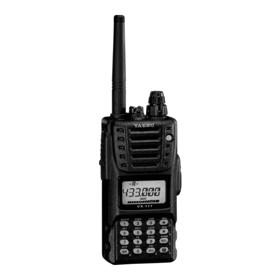
UHF FM TRANSCEIVER
VX-177
O
M
PERATING
ANUAL
VERTEX STANDARD CO., LTD.
4-8-8 Nakameguro, Meguro-Ku, Tokyo 153-8644, Japan
VERTEX STANDARD
US Headquarters
10900 Walker Street, Cypress, CA 90630, U.S.A.
YAESU EUROPE B.V.
P.O. Box 75525, 1118 ZN Schiphol, The Netherlands
YAESU UK LTD.
Unit 12, Sun Valley Business Park, Winnall Close
Winchester, Hampshire, SO23 0LB, U.K.
VERTEX STANDARD HK LTD.
Unit 5, 20/F., Seaview Centre, 139-141 Hoi Bun Road,
Kwun Tong, Kowloon, Hong Kong
Advertisement
Table of Contents

Related Manuals for Yaesu VX-177


Summary of Contents for Yaesu VX-177
- Page 1 4-8-8 Nakameguro, Meguro-Ku, Tokyo 153-8644, Japan VERTEX STANDARD US Headquarters 10900 Walker Street, Cypress, CA 90630, U.S.A. YAESU EUROPE B.V. P.O. Box 75525, 1118 ZN Schiphol, The Netherlands YAESU UK LTD. Unit 12, Sun Valley Business Park, Winnall Close Winchester, Hampshire, SO23 0LB, U.K.
-
Page 2: Table Of Contents
General Description ... 1 Accessories & Options ... 2 Controls & Connections ... 3 Top & Front Panel ... 3 LCD ... 4 Side Panel ... 5 Keypad Functions ... 6 Installation of Accessories ... 8 Antenna Installation ... 8 Installation of FNB-83 Battery Pack ... -
Page 3: General Description
Meter, thus reducing guesswork in setting the squelch threshold. We appreciate your purchase of the VX-177, and encourage you to read this manual thor- oughly, so as to learn about the many exciting features of your exciting new Vertex Stan- dard hand-held transceiver! : IPX-7 Specification for submersibility: 3 ft. -
Page 4: Accessories & Options
Vertex Standard accessories. Consult your Vertex Standard dealer for details regarding these and any newly-available options. Connection of any non-Vertex Standard-approved ac- cessory, should it cause damage, may void the Limited Warranty on this apparatus. PTIONS VX-177 O... -
Page 5: Controls & Connections
This four-conductor miniature jack provides con- nection points for microphone audio, earphone audio, PTT, and ground. Do not allow the VX-177 to become submerged in water while the plastic cover over the MIC/SP jack is removed. VOL/PWR Knob Turn this control clockwise to turn the radio on and to increase the volume. Counter- clockwise rotation into the click-stop will turn the radio off. - Page 6 Battery Saver Active ONNECTORS LCD Memory Channel Number Repeater Shift Direction CTCSS/DSC Operation Key Lock Active S- & PO Meter Automatic Power-Off Active Internet Connection Feature Active Bell Alarm Active Operating Frequency Battery Indicator Emergency Automatic ID (EAI) Feature Active VX-177 O...
-
Page 7: Side Panel
This coaxial DC jack allows connection to an external DC power source (6-16V DC). The center pin of this jack is the Positive (+) connection. Do not allow the VX-177 to become submerged in water while the rubber cap over the EXT DC jack is removed. -
Page 8: Keypad Functions
Frequency entry digit “5.” Selects the CTCSS/DCS Bell ringer repetitions. None Frequency entry digit “8.” Selects the LCD/Keypad Lamp Mode. None Activates the Internet Connection feature. Frequency entry digit “0.” Engages the Set (Menu) Mode. Enables Internet access code selection. VX-177 O... - Page 9 Selects the Memory Bank while in the & H 2 : You can exchange the function between the primary (press key) function and secondary (press [ F ] key +) function, if desired. See page 79 for details. VX-177 O & C ONNECTORS K output level.
-
Page 10: Installation Of Accessories
Open the Battery Pack Latch on the bot- tom of the radio, then slide the battery downward and out from the radio while tilting the Belt Clip out of the way. CCESSORIES FNB-83 B VX-177 O... -
Page 11: Battery Charging
” icon will blink on the LCD display, indicating that the battery pack must be recharged before further use. Avoid recharging Ni-MH batteries before the “ observed, as this can degrade the charge capacity of your Ni-MH battery pack. VX-177 O NSTALLATION OF E-DC-5B CCESSORIES E-DC-6 ”indicator is... -
Page 12: Belt Clip Installation
To install the VX-177 into the Quick-Draw Belt Clip, align the hanger with the Quick- Draw Belt Clip, and slide the VX-177 into its slot until a click is heard (Figure 3). To remove the VX-177 from the Quick-Draw Belt Clip, rotate the VX-177 180 de- grees, then slide the VX-177 out from the Quick-Draw Belt Clip (Figure 4). -
Page 13: Interface Of Packet Tncs
The audio level from the receiver to the TNC may be adjusted by using the VOL knob, as with voice operation. The input level to the VX-177 from the TNC should be adjusted at the TNC side; the optimum input voltage is approximately 5 mV at 2000 Ohms. -
Page 14: Operation
Hi! I’m R. F. Radio, and I’ll be helping you along as you learn the many features of the VX-177. I know you’re anxious to get on the air, but I encour- age you to read the “Operation” section of this manual as thoroughly as possible, so you’ll get the most out of this fantastic new transceiver. -
Page 15: Squelch Adjustment
(subaudible) CTCSS tone. Or, if your friends have radios equipped with DCS (Digital Coded Squelch) like your VX-177 has, try using that mode for silent monitoring of busy channels. - Page 16 VFO S The scanner will stop when it receives a signal strong enough to break through the Squelch threshold. The VX-177 will then hold on that frequency according to the setting of the RESUME ). Press the PTT switch momentarily to “RESUME”...
-
Page 17: Transmission
Once you have set up an appropriate frequency inside the 430 MHz Amateur band on which the VX-177 can transmit, you’re ready to go on the air! These are the most basic steps; more advanced aspects of transmitter operation will be discussed later. -
Page 18: Advanced Operation
DVANCED PERATION Now that you’re mastered the basics of VX-177 operation, let’s learn more about some of the really neat features. In order to prevent accidental frequency change or inadvertent transmission, various as- pects of the VX-177’s DIAL and keypad may be locked out. The possible lockout combi-... -
Page 19: Keypad/Lcd Illumination
Your VX-177 includes a reddish illumination lamp which aids in nighttime operation. The reddish illumination yields clear viewing of the display in a dark environment, with mini- mal degradation of your night vision. Three options for activating the lamp are provided:... -
Page 20: Rf Squelch
5. Press the PTT switch to save the new setting and return to nor- mal operation. The VX-177’s microprocessor includes programming which will measure the current bat- tery voltage. 1. Press the [ F ] key, then press the [ 0 ( SET )] key to enter the Set mode. -
Page 21: Repeater Operation
The VX-177 includes a number of features which make repeater operation simple and enjoyable. The VX-177 has been configured, at the factory, with the repeater shift set to 1.6 MHz, 7.6 MHz, or 5 MHz (USA version). Depending on the part of the band in which you are operating, the repeater shift may be either downward (–) or upward (+), and one of these... -
Page 22: Manual Repeater Shift Activation
If you just have one “odd” split that you need to program, don’t change the “default” repeated shifts using this Set Mode Item. Enter the transmit and receive frequencies separately, as shown on page 29. RPT.MOD .” SHIFT VX-177 O RPT.– ,”... -
Page 23: Vfo Split Mode
PTT switch to transmit, you will observe that VFO-A and VFO-B will reverse positions. The VFO selection indicator “-b-” will blink while the transceiver is transmitting, this means that the VFO Split feature is now activated. VX-177 O EPEATER VFO S VFO.SPL... - Page 24 A split frequency pair set up via the VFO Split feature cannot be stored directly into memory. You can, however, store odd frequency pairs using a different (slightly simpler) procedure. See page 29. VFO S VSP.OFF to “ .” VX-177 O...
-
Page 25: Ctcss/Dcs/Epcs Operation
FM carrier in order to activate the repeater. This helps prevent false activation of the repeater by radar or spurious signals from other transmitters. This tone system, called “CTCSS” (Continuous Tone Coded Squelch System), is included in your VX-177, and is very easy to activate. -
Page 26: Dcs Operation
CTCSS. The DCS Encoder/Decoder is built into your VX-177, and operation is very similar to that just described for CTCSS. Your repeater system may be configured for DCS;... -
Page 27: Tone Search Scanning
When you release the MONI key, Tone Scanning will resume after about a second. Tone Scanning works either in the VFO or Memory modes. VX-177 O CTCSS/DCS/EPCS O DCS O ” will appear on the display; in the case of DCS,... -
Page 28: Epcs (Enhanced Paging & Code Squelch)
CTCSS/DCS/EPCS O EPCS E The VX-177 includes an Enhanced CTCSS tone encoder/decoder and a dedicated micropro- cessor providing paging and selective calling features. This allows you to place a call to a specific station (Paging), and to receive calls of your choice directed only to you (Code Squelch). -
Page 29: Ctcss/Dcs/Epcs Bell Operation
” icon will blink on the display. CTCSS/DCS/EPCS B During CTCSS Decode, DCS, or EPCS operation, you may set up the VX-177 such that a ringing “bell” sound alerts you to the fact that a call is coming in. Here is the procedure for activating the CTCSS/DCS/EPCS Bell: 1. -
Page 30: Split Tone Operation
CTCSS/DCS/EPCS O The VX-177 can be operated in a Split Tone configuration via the Set mode. 1. Press the [ F ] key, then press the [ 0 ( SET )] key to enter the Set mode. 2. Rotate the DIAL knob to select Set Mode Item 43: 3. -
Page 31: Memory Mode
The VX-177 provides a wide variety of memory system resources. These include: 200 “Standard” memory channels, numbered “ A “Home” channel, providing storage and quick recall of one prime frequency. 10 sets of band-edge memories, also known as “Programmable Memory Scan” chan- nels, labeled “... -
Page 32: Memory Recall
[ REV ( HOME )] key momentarily while operating either in the VFO or MR mode. L1 U1 REV HM from “ “USA” V VX-177 O [ 4 ( RPT )] [ F]. L10 U10 ” through “ .”) = “201,”... -
Page 33: Labeling Memories
(alpha-numeric “Tag”) display. To disable the alpha-numeric Tag (enabling the frequency display): 1. Set the VX-177 to the “MR” (Memory Recall) mode, and recall the memory channel on which you wish to disable the alpha-numeric Tag. 2. Press the [ F ] key, then press the [ 0 ( SET )] key to enter the Set mode. -
Page 34: Memory Offset Tuning
Once you have recalled a particular memory channel, you may easily tune off that channel, as though you were in the “VFO” mode. 1. With the VX-177 in the “MR” (Memory Recall) mode, select the desired memory channel. 2. Press the [ MR ( SKIP )] key momentarily to activate the “Memory Tuning”... -
Page 35: Memory Bank Operation
The large number of memories available in the VX-177 could be difficult to utilize without some means of organizing them. Fortunately, the VX-177 includes provision for dividing the memories into as many as ten Memory Groups, so you can categorize the memories in a manner convenient to you. -
Page 36: Moving Memory Data To The Vfo
2. Press and hold in the MONI switch (just below the PTT switch) while turning the radio on. 3. Rotate the DIAL knob to select the “ press the [ F ] key. To return to normal operation, repeat the above power-on procedure. F5 M-ONLY ” option, then VX-177 O... - Page 37 VX-177 O...
-
Page 38: Scanning
CANNING The VX-177 allows you to scan just the memory channels, the entire operating band, or a portion of that band. It will halt on signals encountered, so you can talk to the station(s) on that frequency, if you like. -
Page 39: Vfo Scanning
The VX-177 provides two VFO scanning functions: “Manual VFO Scanning” and “Pro- grammed VFO Scanning.” Manual VFO Scan 1. Select the VFO mode by pressing the [ VFO ( PRI )] key, if necessary. 2. Press and hold in either the [ ( MHz )] or [ ( MHz )] key for one second to initiate upward or downward scanning, respectively. -
Page 40: Memory Scanning
DIAL knob in the MR mode, whether or not it is locked out of the scanning loop). SKIP .” The current Memory ONLY VX-177 O ” se- ” in step 3 above (the “Skipped”... -
Page 41: Preferential Memory Scan
Preferential Memory Scan The VX-177 also allows you to set up a “Preferential Scan List” of channels which you can “flag” within the memory system. These channels are designated by a blinking “ ” icon when you have selected them, one by one, for the Preferential Scan List. -
Page 42: Memory Bank Scan
6. To remove a Memory Bank from the Memory Bank Link Scan, repeat steps 2 and 3 above, to delete the “decimal point” from the Memory Bank number indication. BANK 1 BANK10 ” ~ “ ” and “ ” of the Memory Bank BAN.K 2 VX-177 O ”) you wish to sweep using... -
Page 43: Pms
(Band Limit) Memory Scan. Scanning will now be limited within the just-programmed range. 6. 10 pairs of Band Limit memories, labeled L1/U1 through L10/U10 are available. You therefore can set upper and lower operation limits in multiple segments on the band, if you like. VX-177 O CANNING PMSxx... -
Page 44: (Dual Watch)
4. Press [ F ] [ VFO ( PRI )] again to disable the Memory Priority mode. When the Memory Bank feature is activated, the VX-177 will check the lowest num- bered memory channel in the current Memory Bank as the Priority Channel. - Page 45 2. Press the [ F ] key, then press and hold in the [VFO(PRI)] key for one second. The VX-177 will now periodically change from VFO-A frequency to the VFO-B frequency, checking for activity on each VFO for 0.2 second interval.
-
Page 46: Automatic Lamp Illumination On Scan Stop
5. When you have made your selection, press the PTT switch to save the setting and exit to normal operation. The VX-177 will automatically “beep” when a band edge is encountered during scanning (either in standard VFO scanning or during PMS operation). You may also enable this feature (band edge beeper) to operate when the frequency reaches the band edge while tuning using the DIAL knob. - Page 47 VX-177 O...
-
Page 48: Emergency Feature
MERGENCY EATURE The VX-177 includes an “Emergency” feature which may be useful if you have someone monitoring on the same frequency as your transceiver’s “Home” channel. See page 30 for details on setting up the Home channel. The “Emergency” feature is activated by pressing and holding in the [ 4 ( RPT )] key for one second. -
Page 49: Emergency Automatic Id (Eai) Feature
The Emergency Automatic ID (EAI) Feature has two operating modes: (1) Interval mode and (2) Continuous mode. In the Interval mode, when the VX-177 receives the CTCSS tone pair which is stored in the Receiving Pager Code Memory (configured via Set Mode Item 18: ECS.CDR) on the frequency which is stored in Memory Channel “200”... - Page 50 When the Emergency Automatic ID feature is activated, the “ icon will blink in the LCD. The VX-177 will ignore the EAI feature when the (1) the squelch is open, (2) there is an incoming the signal on the operating frequency, or (3) the operat- ing frequency is the same as the frequency which is stored in the Memory Channel “200.”...
-
Page 51: Smart Search Operation
Smart Search is a great tool when visiting a city for the first time. You don’t need to spend hours looking up repeater frequencies from a reference guide- book. . .just ask your VX-177 where the action is! VX-177 O... -
Page 52: Internet Connection Feature
NTERNET ONNECTION FEATURE The VX-177 can be used to access a “node” (repeater or base station) which is tied into the Vertex Standard WIRES™ (Wide-Coverage Internet Repeater Enhancement System) net- work, operating in the “SRG” (Sister Radio Group) mode. Details may be found at the WIRES-II Web site: http://www.vxstd.com/en/wiresinfo-en/. - Page 53 [ 0 ( SET )] key, while you are transmitting, to send out the selected DTMF string (to establish the link to the desired Internet-link mode). To return to the WIRES™ mode, repeat steps 3 - 6 above, selecting “ VX-177 O NTERNET ONNECTION FEATURE I NET INT.MEM...
-
Page 54: Arts (Automatic Range Transponder System)
“ that the other station’s polling code was received in response to yours. ” indication. ” display on the LCD below the operat- IN.RNG ” to confirm ™ in order to resume VX-177 O... - Page 55 4. Rotate the DIAL knob to select the desired ARTS™ Beep mode (see above). 5. When you have made your selection, press the PTT switch to save the new setting and exit to normal operation. VX-177 O AR INT AR BEP...
-
Page 56: Cw Identifier Setup
12. Press the PTT switch to save the settings and exit to normal operation. You may check your work by monitoring the entered callsign. To do this, repeat steps 1- 7 above, then press the MONI switch. CW WRT CWID VX-177 O... -
Page 57: Dtmf Operation
The VX-177’s 16-button keypad allows easy DTMF dialing for Autopatch, repeater con- trol, or Internet-link access purposes. Besides numerical digits [ 0 ] through [ 9 ] , the keypad includes the [ ] and [ # ] digits, plus the [ A ] , [ B ] , [ C ] , and [ D ] tones often used for repeater control. -
Page 58: To Send The Telephone Number
DTMF memory string; with PTT switch pressed) and the instant when the first DTMF digit is sent, using Set Mode Item 15: [ 9 ( DTMF )] again. The “ ” icon will ap- DT DLY . See page 75 for details. VX-177 O CODE ” indi-... -
Page 59: Dtmf Pager Operation
DTMF P AGER The VX-177 allows you to utilize a DTMF (Dual-Tone, Multi-Frequency) tone encoder/ decoder, with a dedicated microprocessor providing paging and selective calling features now that you've installed the optional FTD-7 DTMF Paging Unit. This capability allows you to make a call to a specific station (Paging), and to receive calls of your choice di- rected only to you (Code Squelch). - Page 60 “ ” in step 4 above. During DTMF Pager operation, you may set up the VX-177 such that a ringing “Bell” sound alerts you to the fact that a call is coming in, as described previously. See page 27 of the Operating Manual for details.
- Page 61 ANI code after the 3-digit DTMF pager code. You may scroll the received ANI code by rotating the DIAL knob. 8. To disable the ANI feature, just repeat the above procedure, ro- tating the DIAL knob to select “ VX-177 O PERATION R ANI.WRT .”...
-
Page 62: Miscellaneous Settings
ISCELLANEOUS The VX-177 provides a security password feature which can minimize the chance that your transceiver could be used by an unauthorized party. When the password feature is activated, the radio will ask for the four digit password to be entered when the radio is first turned on. -
Page 63: Programming The Key Assignment
Default VX-177 Set Mode Items have been assigned (at the factory) to the [ 7 ( P1 )] and [ 8 ( P2 )] keys. These may be changed by the user, if you wish to assign another Set Mode Item to either or both of these keys. -
Page 64: Receive Battery Saver Setup
ISCELLANEOUS An important feature of the VX-177 is its Receive Battery Saver, which “puts the radio to sleep” for a time interval, periodically “waking it up” to check for activity. If somebody is talking on the channel, the VX-177 will remain in the “active” mode, then resume its “sleep”... -
Page 65: Disabling The Tx/Busy Indicator
Rotate the VOL/PWR knob counter-clockwise to the “off” position, then clockwise out of the click-stop, to turn the radio on after an APO shutdown. VX-177 O ISCELLANEOUS TX/BUSY I BSY.LED LED.OFF... -
Page 66: Transmitter Time-Out Timer (Tot)
4. Rotate the DIAL knob to set this Set Mode Item to “ (thus activating the BCLO feature). 5. When you have made your selection, press the PTT switch to save the new setting and exit to normal operation. ETTINGS BCLO BCLO BCL. ON ” VX-177 O... -
Page 67: Dcs Code Inversion
4. When you have made your selection, press the PTT switch to save the new setting and exit to normal operation. 5. Remember to restore the default setting to “ Normal) when done. VX-177 O ISCELLANEOUS DCS C ® ®... -
Page 68: Changing The Tx Deviation Level
The VX-177 includes a simple method of accomplishing this: 1. Press the [ F ] key, then press the [ 0 ( SET )] key to enter the Set mode. -
Page 69: Reset Procedures
4. Press the [ F ] key momentarily to complete the reset procedure. The “F5” option is used for setting up the “Memory Only” mode, and “F6” is used for Cloning. See page 34 for details regarding the memory Only mode, and the next section regarding Cloning. VX-177 O ESET ROCEDURES... -
Page 70: Cloning
The VX-177 includes a convenient “Clone” feature, which allows the memory and con- figuration data from one transceiver to be transferred to another VX-177. This can be particularly useful when configuring a number of transceivers for a public service opera- tion. - Page 71 VX-177 O...
-
Page 72: Set Mode
The VX-177 Set Mode, already described in parts of many previous chapters, is easy to activate and set. It may be used for configuration of a wide variety of transceiver param- eters, some of which have not been detailed previously. Use the following procedure to activate the Set Mode: 1. - Page 73 56 [ PAG.COD ] Setting the Pager Code for the DTMF Pager. 57 [ PAG.ABK ] Enables/Disables the Answer Back function of the DTMF Pager. VX-177 O EMG.BEP / EMG.LMP / EMG.B+L / EMG.CWT / EMG.C+B / EMG.C+L / EMG.ALL / OFF INT.OFF / INT.COD / INT.MEM...
- Page 74 200 MS / 300 MS / 500 MS / 1 S / 2 S / OFF SAV.OFF / SAV. ON INT.OFF / INT.COD / INT.MEM CODE 0 - CODE 9, CODE A - CODE F, ( CODE 1 ) d1 - d9 VX-177 O...
- Page 75 Program the ANI Identifier. Enables/Disables the ANI function. Setting the Pager Code for the DTMF Pager. Enables/Disables the Answer Back function of the DTMF Pager. VX-177 O 6 [ BEEP ] 25 [ LAMP ] 26 [ LOCK ] 27 [ M/T-CL ]...
- Page 76 KEY+SC: The beeper sounds when you press any key, or when the scanner stops. KEY: The beeper sounds when you press any key. OFF: Beeper is disabled. Set Mode Item 7 BELL Function: Selects the number of CTCSS/DCS Bell ringer repetitions. Available Values: OFF/1T/3T/5T/8T/CONT (Continuous ringing) Default: OFF VX-177 O...
- Page 77 Function: Setting of the DTMF Autodialer Sending Speed. Available Values: 50MS (high speed)/100MS (low speed) Default: 50MS VX-177 O DCS CODE 023 025 026 031 032 036 043 047 051 053 054 065 071 072 073 074 114 115 116 122...
- Page 78 When the radio is set to the EMG.CWT, EMG.C+B, EMG.C+L, or EMG.ALL mode, the radio will be instructed to send “DE (your callsign)” after the sending of the SOS message, if your callsign is entered via Set Mode Item 10: CWID VX-177 O...
- Page 79 Disables the Keypad/LCD lamp. Set Mode Item 26 LOCK Function: Selects the Control Locking lockout combination. Available Values: LK KEY/LKDIAL/LK K+D/LK PTT/LK P+K/LK P+D/LK ALL Default: LK K+D Note: “K” = “Key;” “D” = “Dial;” and “P” = “PTT.” VX-177 O...
- Page 80 BUSY: The scanner will hold until the signal disappears, then will resume when the car- rier drops. HOLD: The scanner will stop when a signal is received, and will not restart. TIME: The scanner will hold for the five seconds, then resume whether or not the other station is still transmitting. VX-177 O...
- Page 81 CONT: The transceiver makes a sweep in each direction as with the “SINGLE” mode, but if all 31 channels are not filled after the first sweep, the radio continues sweeping until they are all filled. VX-177 O...
- Page 82 “DCS” parameter while configuring Set Mode Item 44: DCS Encode only. T DCS: Encodes a CTCSS tone and Decodes a DCS code. D TSQL: Encodes a DCS code and Decodes a CTCSS tone. Select the desired operating mode from the selections shown above. VX-177 O...
- Page 83 Available Values: SAV.OFF/ SAV. ON Default: SAV.OFF Set Mode Item 50 VFO.SPL Function: Enables or disables “VFO Split” operation. Available Values: VSP.OFF/VSP. ON Default: VSP.OFF VX-177 O SPLIT regarding additional selections available during CTCSS TONE FREQUENCY ( Hz ) 67.0 69.3 82.5...
- Page 84 Set Mode Item 56 PAG.COD Function: Setting the Pager Code for the DTMF Pager. See page 55 for details. Set Mode Item 57 PAG.ABK Function: Enables/Disables the Answer Back function of the DTMF Pager. Available Values: ABK.OFF/ABK. ON Default: ABK. OFF VX-177 O...
-
Page 85: Specifications
MHz amateur band only. Frequency ranges and functions will vary according to trans- ceiver version; check with your dealer. VX-177 O RX 430 - 440 MHz or 420 - 470 MHz TX 430 - 440 MHz or 430 - 450 MHz 5/10/12.5/15/20/25/50/100 kHz... -
Page 86: Installation Of The Ftd-7 Dtmf Pager Unit
2 seconds, along with the current DC supply voltage, when you turn the radio on. Peel off the Connector Caution Seal FTD-7 DTMF P Press the Optional Unit VX-177 O ” Affix the supplied Caution Seal... - Page 87 1. Changes or modifications to this device not expressly approved by VERTEX STANDARD could void the user’s authorization to operate this device. 2. This device complies with part 15 of the FCC Rules. Operation is subject to the following two conditions: (1) This device may not cause harmful interference, and (2) this device must accept any interference including received, interference that may cause undesired operation.
- Page 88 Copyright 2005 Printed in Japan VERTEX STANDARD CO., LTD. All rights reserved. No portion of this manual may be reproduced without the permission of VERTEX STANDARD CO., LTD. 0511X-0K...
Need help?
Do you have a question about the VX-177 and is the answer not in the manual?
Questions and answers