Table of Contents
Advertisement
1
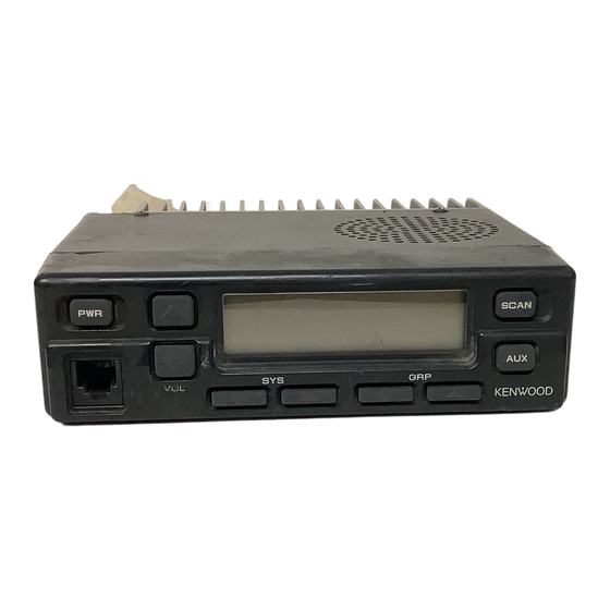
800MHz/900MHz
FM
TRANSCEIVER
O 1994-8 PRINTED IN JAPAN
B51-8281-00( N
)
121 9
C'
Microphone
SERVICE MANUAL
BLOCK DIAGRAM
..........................................
:;..:.:.$@$::' : ,
'~'\,'.'- "!?$LU~CO
.i@&4170-XX)
...................................
.
'i
;a.,
"
'
66
...................
LEVEL DIAGRAM
...............................
. . . .
2b
. .
. . . . . .
:FX-R%~?ONIT 1x57-4590-XXI (BIZ)
....................
67
.
.
.
.,
,
G
.........................................
.
CIRCUIT DESCRIPTION
27
,
....................
" .
T X - R X ; U N I ~ ~ X ~ ~ - ~ ~ ~ O - X X )
(A121
7 1
SEMICONDUCTOR DATA
..................................
34
SCHEM&TIC ~ ~ A G R A M
.........................................
77
.
,
.....................
DESCRIPTION .OF COMPON~NTS
:;:b
39.'
SPECIFICA~:IONS
.............................................
:.. ....
83
...........
.........................................
....
,;-\I
PARTS LIST
.......
41
KT-19 (ACCESSORY CONNECTION CABLE1
BACK COVER
...
,
EXPLODED VIEW
............................................
55
..................
. .
KDD-4 (D'rMF DECODER)
BACK COVER
.........................................
PACKING
......................
:
56
KPG-25D (PROGRAMMING DISK)
....
BACK COVER
a
Advertisement
Table of Contents

Related Manuals for Kenwood 941


Summarization of Contents
GENERAL
PERSONNEL SAFETY
Essential safety precautions for operating and servicing the equipment.
PRE-INSTALLATION CONSIDERATIONS
Steps and requirements before installing the transceiver.
PRE-INSTALLATION CHECKOUT
Procedure for checking receiver and transmitter operation before installation.
SYSTEM SET-UP
Choose the type of transceiver
Guidance on selecting the appropriate transceiver model.
OPERATING FEATURES
General Transceiver Features
Summary of programmable features for general transceiver operation.
Transceiver Controls and Indicators
Explanation of front panel controls and indicators.
System Scan
Details on how system scan functionality operates.
AUTO TEL
Procedure for making telephone interconnect calls automatically.
Conventional System Operation
Features and operation for conventional system mode.
Horn Alert
Configuration and operation of the horn alert feature.
Transceiver Programming
Data Program Mode
Instructions for entering and using data program mode.
INSTALLATION
Installing the KDD-4 in the transceiver
Step-by-step guide for installing the KDD-4 unit.
Accessory Connection Cable (KCT-19: Option)
Details on the accessory connection cable and its installation.
Ignition Sense Cable (KCT-18: Option)
Information on the ignition sense cable and its function.
External Speaker
Procedures for connecting external speakers.
Fitting the Control Panel Upside Down
Instructions for mounting the control panel in an upside-down orientation.
CIRCUIT DESCRIPTION
2. Circuit Configuration by Frequency
Explanation of how the circuit handles different frequencies.
3. Receiving System
Detailed description of the receiver system operation.
4. Transmitter System
Detailed description of the transmitter system operation.
5. Frequency Synthesizer Unit
Description of the frequency synthesizer and PLL system.
6. Control unit
Description of the control unit functions and components.
7. LCD Assembly
Description of the LCD assembly, including CPU and display.
SEMICONDUCTOR DATA
Level Adjuster : M62363FP (TX-RX Unit IC6)
Technical data for the Level Adjuster IC.
Audio Power Amplifier: LA4422 (TX-RX Unit IC11)
Technical data for the Audio Power Amplifier IC.
Microprocessor : 78312AGF3563BE (TX-RX Unit IC209)
Technical data for the Microprocessor IC.
PLL System : SC370651F or MC145190F-K (PLL/VCO IC1)
Technical data for the PLL System IC.
DESCRIPTION OF COMPONENTS
TX-RX UNIT (X57-4590-XX) -10: TK-940 -11: TK-941
List and description of components for the TX-RX unit.
PLL/VCO (X58-4170-XX) -10: TK-940 -11: TK-941
List and description of components for the PLL/VCO unit.
PARTS LIST
CAPACITORS
Detailed list of capacitors used in the unit.
RESISTORS
Detailed list of resistors used in the unit.
ADJUSTMENT
Test Equipment Required for Alignment
List of test equipment and their specifications for alignment.
2. Display section (LCD)
Explanation of the LCD display indicators and their meanings.
User mode
Description of user mode key functions and operations.
Dealer mode
Description of dealer mode key functions and operations.
Tuning mode
Description of tuning mode key functions and operations.
Receiver section
Adjustment procedures for the receiver section.
Transmitter Section
Adjustment procedures for the transmitter section.
TERMINAL FUNCTION
TX-RX UNIT (X57-4590-XX) (A/2): TX-RX section
Terminal pin functions for the TX-RX unit's TX-RX section.
TX-RX UNIT (X57-4590-XX) (B/2): Control section
Terminal pin functions for the TX-RX unit's control section.
KDD-4
Terminal pin functions for the KDD-4 decoder.
PC BOARD VIEWS
LCD ASSY (B38-0731-05) Component side view
Component layout view of the LCD ASSY.
PLL/VCO (X58-4170-XX) (A/2) -10: TK-940 -11: TK-941 Component side view
Component layout view of the PLL/VCO unit.
TX-RX UNIT (X57-4590-XX) (B/2) Component side view -10: TK-940 -11: TK-941
Component layout view of the TX-RX unit.
SCHEMATIC DIAGRAM
TX-RX UNIT (TX-RX SECTION) (X57-4590-XX) (A/2)
Schematic diagram of the TX-RX unit's TX-RX section.
TX-RX UNIT (CONTROL SECTION) (X57-4590-XX) (B/2)
Schematic diagram of the TX-RX unit's control section.
Need help?
Do you have a question about the 941 and is the answer not in the manual?
Questions and answers