Sign In
Upload
Manuals
Brands
Kenwood Manuals
Transceiver
941
Kenwood 941 Manuals
Manuals and User Guides for Kenwood 941. We have
1
Kenwood 941 manual available for free PDF download: Service Manual
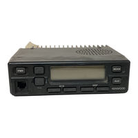
Kenwood 941 Service Manual (85 pages)
800MHz/900MHz FM TRANSCEIVER
Brand:
Kenwood
| Category:
Transceiver
| Size: 6.27 MB
Table of Contents
Contents
1
General
2
Introduction
2
Pre-Installation Considerations
2
Testing
2
Planning the Installation
3
Installation Planning - Control Stations
3
Service
3
System Set-Up
4
Operating Features
5
Transceiver Controls and Indicators
5
General Transceiver Features
5
Trunked System Features
5
Front Panel Displays and Indicators
6
Details of Features
7
System Scan
7
System Lockout
7
Drop-Out Delay Time (Scan Resume Time)
7
Systemigroup Revert
8
Scan Message Wait
8
Call Indicator
8
Time-Out Timer
8
Free System Ringback
9
System Search
9
Transpond
9
Preferred System Revert
9
Auto Tel
10
Audible User Feedback Tones
10
Clear-To-Talk
10
Conventional System Operation
11
External Decoder (KDD-4 Option)
11
Horn Alert
12
System Scan Type
12
Data Port
12
Transceiver Programming
13
KPG-4 Description
13
Programming Software Description
13
Data Program Mode
13
Clone Mode
14
Description of each Modes
14
Dealer Mode
14
Panel Tuning Mode
15
Installation
16
Installing the Signaling Unit
16
KDD-4Assembly
16
Installing the KDD-4 in the Transceiver
17
Setting the KDD-4 Code (DTMF)
18
Accessory Connection Cable
18
Installing the KCT-19 in the Transceiver
18
Jumper Setup Charts
18
Terminal Function
19
Ignition Sense Cable (KCT-18 : Option)
20
Connecting the KCT-18 T O the Transceiver
20
Modifying the Transceiver
20
R5 and R6 Setup Chart
20
External Speaker
21
KES-3: Option
21
KES-4: Option
21
Fitting the Control Panel Upside down
22
Block Diagram
23
Level Diagram (TK-490)
25
Level Diagram (TK-491)
26
Circuit Description
27
Overview
27
Circuit Configuration by Frequency
27
Receiving System
27
Audio Amplifier Unit
28
Squelch Circuit
28
Transmitter System
29
Microphone Amplifier
29
Final Amplifier
29
APC Circuit
29
Frequency Synthesizer Unit
30
Pll
30
PLL Unlock
30
Control Unit
31
Memory Circuit
31
TX Encode Data
31
RX Decode Data
31
PLL Data Output
32
Horn Control
32
Power Supply Circuit
32
LCD Assembly
33
Cpu
33
Power Switch Circuit
33
Tone Generator
33
Semiconductor Data
34
Level Adjuster : M62363FP (TX-RX Unit IC6)
34
Audio Power Amplifier : LA4422 (TX-RX Unit IC11)
34
EEPROM : At24C02Nlos12.7 (TX-RX Unit IC201)
35
Microprocessor : 78312AGF3563BE (TX-RX Unit IC209)
36
Microprocessor : 75308BGK740BE9 (LCD Assy IC2)
37
PLL System : SC370651F or MC145190F-K (PLLIVCO ICI)
38
Description of Components
39
Parts List
41
Exploded View
55
Packing
56
Adjustment
57
Test Equipment Required for Alignment
57
Adjustment Location
58
Common Section
59
Receiver Section
60
Transmitter Section
61
Adjustment Point
62
Specifications
65
KCT-19 (Accessory Connection Cable)/ KDD-4 (DTMF Decoder)/ KPG-25D (Programming Disk)
66
LCD ASSY (638-0731 -05) Component Side View
67
LCD ASSY (B38-0731-05) Foil Side View
67
PC Board Views
68
TX-RX Unit (X57-4590-XX) (A/2) Component Side View -10: TK-940 -11: TK-941
73
TX-RX Unit (X51-4590-XX) 11\12) Foil Side View -10 : TK-940 -11 : TK-941
75
Schematic Diagram
79
Advertisement
Advertisement
Related Products
Kenwood 9190DABS
Kenwood 901603
Kenwood 144MHz FM TRANSCEIVER K2E
Kenwood 144MHz FM TRANSCEIVER K2ET
Kenwood 17095
Kenwood 229900
Kenwood 2754588
Kenwood 3206
Kenwood 32253110
Kenwood 37333120
Kenwood Categories
Car Receiver
Transceiver
CD Player
Amplifier
Receiver
More Kenwood Manuals
Login
Sign In
OR
Sign in with Facebook
Sign in with Google
Upload manual
Upload from disk
Upload from URL