Advertisement
Advertisement
Table of Contents

Related Manuals for N-Tron 306FX2 Series


Summarization of Contents
General Safety Information
General Warnings
General safety warnings include precautions for service, operation with covers removed, air vents, and hazardous environments.
Safety Warnings
Electrical Safety Precautions
Electrical safety warnings cover hazards during live circuits, power cable removal, operation with covers, grounding, lightning, servicing, air vents, and polarity.
Laser Safety
Laser safety for FXE products includes a caution for Class 1 laser products and not to stare into the laser beam.
Hazardous Location Installation Requirements
Installation Requirements
Requirements for Class I, Div 2 installations include warnings on live circuits, local codes, current limiting fuses, UL approved devices, wiring, and operating voltage.
300 Series Industrial Ethernet Switches
Key Features
Key features of the 300 Series Industrial Ethernet Switches include IEEE compliance, NEMA TS1/TS2 compliance, ABS type approval, extended environmental specs, and DIN-Rail mounting.
Package Contents and Preparation
Package Contents
Lists the items included in the Ethernet Switch package: the 300 Series Unit and the N-Tron Product CD.
Installation and Unpacking
Instructions for unpacking and initial installation setup, including critical safety warnings.
Mounting Options
DIN-Rail Mounting
Instructions for installing and removing units from 35mm industrial DIN-Rail, including clearance requirements.
Alternative Mounting Solutions
Alternative mounting solutions include Panel Mount Assemblies (300-PM, 900-PM) and a Universal Rack Mount Kit (URMK).
Front Panel Details
Front Panel Indicators and LEDs
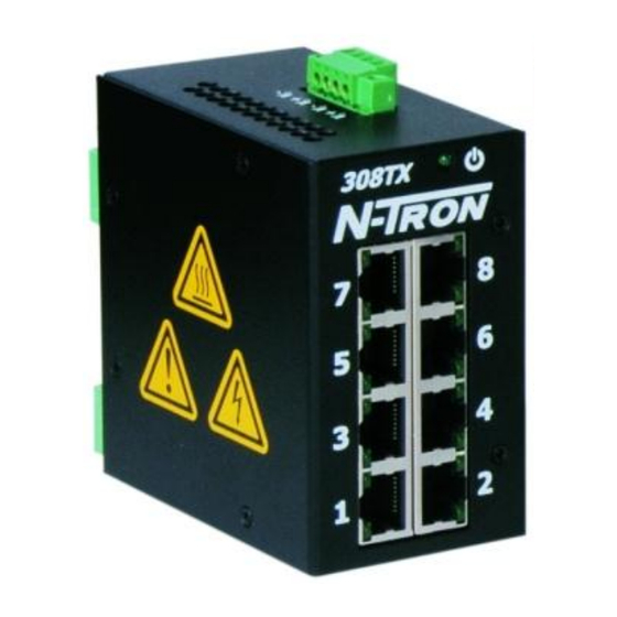
Details the front panel components, including LNK, TX, RX, ACT LEDs for fiber ports, and RJ45 ports with dual LEDs for link/activity.
Power Supply and Connection
Applying Power
Procedure for applying DC power, including connecting cables to the voltage input plug, torque specifications, and LED verification.
Grounding and Cabling Practices
Switch Grounding Techniques
Explains grounding philosophy, methods for connecting to earth ground via drain wire, and verifying voltage differences.
Shielded Cable Usage
Guidelines for using shielded Cat5e cables, including connecting shields at one end to prevent ground loops.
Cable Specifications
RJ45 Connector Crimp Specifications
Illustration and specifications for CAT5e cable wiring according to EIA 568B standards for RJ45 connectors.
Connecting and Troubleshooting
Connecting the Unit
Instructions for connecting fiber optic and Ethernet cables, including TX/RX port connections and cable types for different speeds.
Troubleshooting Steps
Steps to troubleshoot issues, including checking power LED, link LEDs, cabling, and fiber optic connections.
Key Specifications
Product Specifications Summary
Summary of physical, electrical, environmental, network media, fiber transceiver, connector, and wiring clearance specifications for N-TRON 300 Series switches.
Regulatory and Warranty Information
Regulatory Approvals
Details safety approvals for hazardous locations, EMI/EMS standards, conducted low frequency standards, and environmental test compliance.
Warranty Overview
States that N-TRON products carry a 3-year limited warranty from the date of purchase.
N-TRON Limited Warranty
Warranty Terms and Conditions
Detailed terms of the limited warranty, including coverage, service authorization, advance replacement, and limitations of liability.
Need help?
Do you have a question about the 306FX2 Series and is the answer not in the manual?
Questions and answers