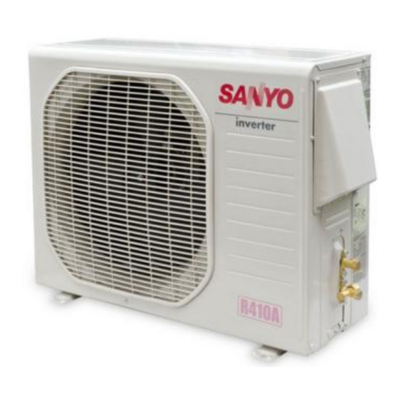
Sanyo CL1852 Service Manual
Split system air conditioner
Hide thumbs
Also See for CL1852:
- Technical & service manual (83 pages) ,
- Installation instructions manual (27 pages) ,
- Specification sheet (3 pages)
Table of Contents
Advertisement
Advertisement
Table of Contents

Summarization of Contents
2. SPECIFICATIONS
(1) Unit Specifications
Detailed specifications for the air conditioning unit, including power, capacity, and features.
(2) Major Component Specifications - Indoor Unit
Key specifications for the indoor unit's major components like fan motor, heat exchanger, and controls.
(2) Major Component Specifications - Outdoor Unit
Key specifications for the outdoor unit's major components like compressor, fan motor, and heat exchange.
(3) Other Component Specifications - Indoor Unit
Detailed specifications for other indoor unit components such as power transformer, thermistors, relays, and drain pump.
(3) Other Component Specifications - Outdoor Unit
Detailed specifications for other outdoor unit components including power transformer, thermistors, and relays.
3. DIMENSIONAL DATA
(1) Indoor Unit XS1852
Provides detailed dimensions and mounting information for the XS1852 indoor unit in inches and millimeters.
(2) Outdoor Unit C1852, CL1852
Provides detailed dimensions and connection port information for the C1852 and CL1852 outdoor units in inches.
4. PERFORMANCE CHARTS
(1) Operating Current
Charts showing operating current variations based on indoor and outdoor air temperatures for different voltage configurations.
7. INSTALLATION INSTRUCTIONS
1) Tubing Length
Guidelines for refrigerant tubing length, including limits for length and elevation difference between units.
2) Selecting the Installation Site
Recommendations and precautions for selecting suitable indoor and outdoor installation locations to ensure optimal performance.
3) Baffle Plates for the Outdoor Unit
Guidance on using baffle plates for specific outdoor unit models (CLxx) in high wind conditions.
4) Electrical Wiring
General precautions and rules for safe and correct electrical wiring, including grounding and wire sizing.
Recommended Wire Length and Diameter for Power Supply System
Recommended wire gauge and length for power supply and inter-unit wiring, along with wiring system diagrams.
8. ELECTRICAL DATA
Electrical characteristics
Presents electrical characteristics for indoor, outdoor, and complete units, including current, power, and starting amperes.
9. ELECTRICAL WIRING DIAGRAMS
(1) Indoor Unit
Detailed electric wiring diagram for the XS1852 indoor unit, illustrating component connections and terminal layouts.
(2) Outdoor Unit
Electric wiring diagrams for the C1852 and CL1852 outdoor units, showing component connections and power supply.
10. PROCESSES AND FUNCTIONS
(1) Room Temperature Control
Explains how the unit controls room temperature by cycling the compressor based on thermostat settings.
(2) Freeze Prevention
Describes the freeze prevention mechanism to protect the indoor coil from freezing and maintain efficiency.
(3) Drain Pump Control
Details the operation of the drain pump, triggered by compressor activity or float switch status.
(4) Outdoor Fan Speed Control
Explains the low ambient fan speed control for the outdoor unit to protect the compressor.
11. SERVICE PROCEDURES
(1) Troubleshooting
General troubleshooting steps, focusing on power supply and wiring checks as initial diagnostics.
(2) Air Conditioner does not Operate
Diagnoses issues when the unit fails to operate, covering circuit breaker trips, power failures, and remote control problems.
3) Outdoor Unit does not Run
Troubleshooting guide for scenarios where the outdoor unit fails to operate, checking remote control and temperature settings.
4) Indoor Unit does not Run
Diagnoses issues when the indoor unit's fan and louver motor do not run, pointing to PCB issues.
9) Poor Cooling
Addresses issues related to insufficient cooling performance, checking air filters, fan speed, and refrigerant levels.
(2) A Sensor is Defective
Details symptoms and checks for defective indoor coil or room temperature sensors affecting unit operation.
(4) Checking the Electrical Components
Procedures for measuring insulation resistance and checking various electrical components for proper function.
2) Checking the Protective Devices
Methods for checking the continuity of thermal protectors and other protective devices within the unit.
3) Checking the Electrical Parts
Procedures for measuring the resistance of electrical parts like transformers, motors, and capacitors.
4) Thermistor Characteristic Curve
Graphs showing the resistance characteristics of room and coil temperature sensors versus temperature.


Need help?
Do you have a question about the CL1852 and is the answer not in the manual?
Questions and answers