Advertisement
- 1 About Your Monitor
- 2 Setting Up the Monitor
- 3 Operating the Monitor
- 4 Troubleshooting
- 5 Notes, cautions, and warnings
- 6 Documents / Resources
About Your Monitor
Package Contents
Your monitor ships with the components shown below. Ensure that you have received all the components and Contact Dell if something is missing.
 NOTE: Some items may be optional and may not ship with your monitor. Some features or media may not be available in certain countries.
NOTE: To set up with any other stand, please refer to the respective stand setup guide for setup instructions.


Product Features
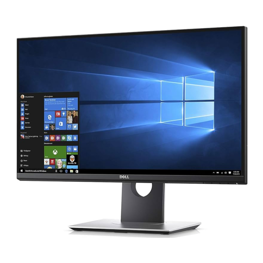
The Dell S2417DG flat panel display has an active matrix, Thin-Film Transistor (TFT), Liquid Crystal Display (LCD) and LED backlight. The monitor features include:
- 60.47 cm (23.8-inch) viewable area (measured diagonally). Resolution: Up to 2560 x 1440 through DisplayPort and HDMI, with full-screen support or lower resolutions.
- Nvidia G-Sync-enabled and 3D Vision Ready monitor, with a extremely high refresh rate of 144 Hz (165Hz with overclock) and a rapid response time of 1 ms.
- Color gamut of 72% NTSC.
- Tilt, Swivel, Pivot, Height Adjustment capability
- Removable stand and Video Electronics Standards Association (VESA™) 100 mm mounting holes for flexible mounting solutions.
- Digital connectivity with DisplayPort and HDMI.
- Equipped with 1 USB upstream port and 4 USB downstream ports.
- Plug and play capability if supported by your system.
- On-Screen Display (OSD) adjustments for ease of set-up and screen optimization.
- The color modes also offers different game modes, including FPS (First-Person Shooter), RTS (Real-Time Strategy), and RPG (Role-Playing Game).
- Software and documentation media includes an Information File (INF), Image Color Matching File (ICM), and product documentation.
- Security lock slot.
- Stand lock.
- Arsenic-Free glass and Mercury-Free for the panel only.
- 0.5 W standby power when in sleep mode.
- Energy Gauge shows the energy level being consumed by the monitor in real time.
- Analog backlight dimming control for flicker-free display.
Identifying Parts and Controls
Front View

| Label | Description |
| 1 | Function buttons (For more information, see Operating the Monitor) |
| 2 | Power On/Off button (with LED indicator) |
NOTE: For displays with glossy bezels the user should consider the placement of the display as the bezel may cause disturbing reflections from surrounding light and bright surfaces.
Back View

| Label | Description | Use |
| 1 | VESA mounting holes (100 mm x 100 mm - behind attached VESA Cover) | Wall mount monitor using VESA-compatible wall mount kit (100 mm x 100 mm). |
| 2 | Regulatory label | Lists the regulatory approvals. |
| 3 | Stand release button | Releases stand from monitor. |
| 4 | Security lock slot | Secures monitor with security lock (security lock not included). |
| 5 | Barcode serial number label | Refer to this label if you need to contact Dell for technical support. |
| 6 | Cable-management slot | Use to organize cables by placing them through the slot. |
Side View

| Label | Description | Use |
| 1 | USB 3.0 port | Connect your USB device.
|
| 2 | USB 3.0 port with PowerShare | Connect your USB device (also supports fast charging). |
| 3 | Headphone-out jack | Connect the headphones. |
Bottom View

Bottom view without monitor stand
| Label | Description | Use |
| 1 | Power cable connector | Connect the power cable (shipped with your monitor). |
| 2 | Stand lock feature | To lock the stand to the monitor using a M3 x 6 mm screw (screw not included). |
| 3 | Line-out port | Connect your speakers.
|
| 4 | DisplayPort | Connect to your computer using the DP cable (shipped with your monitor). |
| 5 | HDMI port | Connect to your computer using the HDMI cable. |
| 6 | USB upstream port | Connect the USB cable (shipped with your monitor) to this port and your computer to enable the USB ports on your monitor. |
| 7 | USB 3.0 ports (2) | Connect USB device.
|
Monitor Specifications
Flat Panel Specifications
| Model | S2417DG |
| Screen type | Active matrix - TFT LCD |
| Panel technology | TN |
| Aspect ratio | 16:9 |
| Viewable image | |
| Diagonal Horizontal, Active Area Vertical, Active Area Area | 604.7 mm (23.8 inches) 526.85 mm (20.74 inches) 296.35 mm (11.67 inches) 156131.99 mm2 (242.04 inch2) |
| Pixel pitch | 0.2058 mm x 0.2058 mm |
| Pixel per inch (PPI) | 123 |
| Viewing angle | 160° (vertical) typical 170° (horizontal) typical |
| Brightness | 350 cd/m² (typical) |
| Contrast ratio | 1000 to 1 (typical) |
| Display screen coating | Anti-Glare with 3H hardness |
| Backlight | LED edgelight system |
| Response time (typical) | 1 ms gray-to-gray |
| Color depth | 16.7 million colors |
| Color gamut | 72%* (CIE1931) |
| Built-in devices |
|
| Connectivity |
|
| Adjustability | |
| Height adjustable stand Tilt Swivel Pivot | 0 to 130 mm -5° to 21° -45° to 45° -90° to 90° |
| Dell Display Manager Compatibility | No |
| Security | Security lock slot (cable lock sold separately) |
* Color gamut (typical) is based on CIE1976 (82%) and CIE1931 (72%) test standards.
Resolution Specifications
| Model | S2417DG |
| Horizontal scan range | 30 kHz to 160 kHz (automatic) |
| Vertical scan range | 30 Hz to 150 Hz (automatic) 165 Hz with overclock |
| Maximum preset resolution | 2560 X 1440 at 165 Hz (with overclock) |
Supported Video Modes
| Model | S2417DG |
| Video display capabilities (HDMI & DP playback) | 480p, 480i, 576p, 720p, 1080p, 576i, 1080i, 1080p, QHD |
Preset Display Modes
HDMI Display Modes
| Display Mode | Horizontal Frequency (kHz) | Vertical Frequency (Hz) | Pixel Clock (MHz) | Sync Polarity (Horizontal/ Vertical) |
| IBM VGA,640 x 480p | 31.5 | 60 | 25.2 | -/- |
| VESA, 720 x 480p | 29.83 | 60 | 26.25 | +/- |
| VESA, 720 x 576p | 29.55 | 50 | 26 | +/- |
| VESA, 800 x 600p | 37.88 | 60 | 40 | +/+ |
| VESA, 1024 x 768p | 48.36 | 60 | 65 | -/- |
| HDTV, 1280 x 720p | 37.5 | 50 | 74.25 | +/+ |
| HDTV, 1280 x 720p | 45 | 60 | 74.25 | +/+ |
| HDTV, 1920 x 1080p | 55.6 | 50 | 141.5 | -/+ |
| HDTV, 1920 x 1080p | 67.5 | 60 | 148.5 | +/+ |
| VESA, 2560 x 1440p | 88.8 | 60 | 241.5 | +/- |
DP Display Modes
| Display Mode | Horizontal Frequency (kHz) | Vertical Frequency (Hz) | Pixel Clock (MHz) | Sync Polarity (Horizontal/ Vertical) |
| VESA, 640 x 480 | 31.5 | 60 | 25.2 | -/- |
| VESA, 800 x 600 | 37.88 | 60 | 40 | +/+ |
| VESA, 1024 x 768 | 48.36 | 60 | 65 | -/- |
| VESA, 2560 x 1440 | 88.8 | 60 | 241.5 | +/- |
| VESA, 2560 x 1440 | 127.4 | 85 | 346.5 | +/- |
| VESA, 2560 x 1440 | 150.9 | 100 | 410.5 | +/- |
| VESA, 2560 x 1440 | 182.9 | 120 | 497.75 | +/- |
| VESA, 2560 x 1440 | 209.5 | 144 | 569.75 | +/+ |
| VESA, 2560 x 1440 | 34.9 | 24 | 95 | +/- |
| VESA, 2560 x 1440 | 232.05 | 150 | 612.61 | +/- |
| VESA, 2560 x 1440 | 240.40 | 155 | 634.66 | +/- |
| VESA, 2560 x 1440 | 240.64 | 160 | 635.28 | +/+ |
| VESA, 2560 x 1440 | 240.74 | 165 | 635.54 | +/+ |
NOTE: This monitor supports NVIDIA G-Sync and NVIDIA 3D Vision Ready. Please visit http://www.geforce.com to know whether your NVIDIA graphics card supports the G-SYNC feature.
Electrical Specifications
| Model | S2417DG |
| Video input signals |
|
| Synchronization input signals | Separate horizontal and vertical synchronization, polarity-free TTL level, SOG (Composite SYNC on green) |
| AC input voltage/frequency/ current | 100 VAC to 240 VAC / 50 Hz or 60 Hz + 3 Hz / 1.5 A (typical) |
| Inrush current |
|
Physical Characteristics
| Model | S2417DG |
| Signal cable type |
|
| Dimensions (with stand) | |
| Height (extended) | 493.9 mm (19.44 inches) |
| Height (compressed) | 363.9 mm (14.33 inches) |
| Width | 540.4 mm (21.28 inches) |
| Depth | 180.0 mm (7.09 inches) |
| Dimensions (without stand) | |
| Height | 322.7 mm (12.70 inches) |
| Width | 540.4 mm (21.28 inches) |
| Depth | 55.8 mm (2.20 inches) |
| Stand dimensions | |
| Height (extended) | 400.8 mm (14.78 inches) |
| Height (compressed) | 354.4 mm (13.95 inches) |
| Width | 242.6 mm (9.55 inches) |
| Depth | 180.0 mm (7.09 inches) |
| Weight | |
| Weight with packaging | 8.23 kg (18.11 lb) |
| Weight with stand assembly and cables | 6.09 kg (13.40 lb) |
| Weight without stand assembly (For wall mount or VESA mount considerations - no cables) | 3.84 kg (8.45 lb) |
| Weight of stand assembly | 1.93 kg (4.25 lb) |
| Front frame gloss | Black Frame - 30 gloss unit (max.) |
Environmental Characteristics
| Model | S2417DG |
| Compliant Standards | |
| |
| Temperature | |
| Operating | 0°C to 40°C (32°F to 104°F) |
| Non-operating |
|
| Humidity | |
| Operating | 10% to 80% (non-condensing) |
| Non-operating |
|
| Altitude | |
| Operating | 5,000 m (16,404 ft) (maximum) |
| Non-operating | 12,192 m (40,000 ft) (maximum) |
| Thermal dissipation |
|
Power Management Modes
If you have VESA's DPM™ compliance display card or software installed in your PC, the monitor can automatically reduce its power consumption when not in use. This is referred to as Power Save Mode*. If the computer detects input from the keyboard, mouse, or other input devices, the monitor automatically resumes functioning. The following table shows the power consumption and signaling of this automatic power saving feature.
| VESA Modes | Horizontal Sync | Vertical Sync | Video | Power Indicator | Power Consumption |
| Normal operation | Active | Active | Active | White | 73 W (maximum)** 33 W (typical) |
| Active-off mode | Inactive | Inactive | Blanked | White (blinking) | Less than 0.5 W |
| Switch off | - | - | - | Off | Less than 0.3 W |
* Zero power consumption in OFF mode can only be achieved by disconnecting the main cable from the monitor.
** Maximum power consumption with max luminance, and USB active.
Pin Assignments
DisplayPort Connector

| Pin Number | 20-pin Side of the Connected Signal Cable |
| 1 | ML0(p) |
| 2 | GND |
| 3 | ML0(n) |
| 4 | ML1(p) |
| 5 | GND |
| 6 | ML1(n) |
| 7 | ML2(p) |
| 8 | GND |
| 9 | ML2(n) |
| 10 | ML3(p) |
| 11 | GND |
| 12 | ML3(n) |
| 13 | GND |
| 14 | GND |
| 15 | AUX(p) |
| 16 | GND |
| 17 | AUX(n) |
| 18 | GND |
| 19 | Re-PWR |
| 20 | +3.3 V DP_PWR |
HDMI Connector

| Pin Number | 19-pin Side of the Connected Signal Cable |
| 1 | TMDS DATA 2+ |
| 2 | TMDS DATA 2 SHIELD |
| 3 | TMDS DATA 2- |
| 4 | TMDS DATA 1+ |
| 5 | TMDS DATA 1 SHIELD |
| 6 | TMDS DATA 1- |
| 7 | TMDS DATA 0+ |
| 8 | TMDS DATA 0 SHIELD |
| 9 | TMDS DATA 0- |
| 10 | TMDS CLOCK+ |
| 11 | TMDS CLOCK SHIELD |
| 12 | TMDS CLOCK- |
| 13 | CEC |
| 14 | Reserved (N.C. on device) |
| 15 | DDC CLOCK (SCL) |
| 16 | DDC DATA (SDA) |
| 17 | DDC/CEC Ground |
| 18 | +5V POWER |
| 19 | HOT PLUG DETECT |
Plug and Play Capability
You can install the monitor in any Plug and Play-compatible system. The monitor automatically provides the computer system with its Extended Display Identification Data (EDID) using Display Data Channel (DDC) protocols so that the system can configure itself and optimize the monitor settings. Most monitor installations are automatic; you can select different settings if desired. For more information about changing the monitor settings, see Operating the Monitor.
Universal Serial Bus (USB) Interface
This section gives you information about the USB ports that are available on the monitor.
NOTE: This monitor is Super-Speed USB 3.0 compatible.
| Transfer Speed | Data Rate | Power Consumption* |
| Super-speed | 5 Gbps | 4.5 W (Max, each port) |
| High speed | 480 Mbps | 4.5 W (Max, each port) |
| Full speed | 12 Mbps | 4.5 W (Max, each port) |
* Up to 2 A on USB downstream port (port with  lightning icon) with BC1.2compliant devices or normal USB devices.
USB Upstream Connector

| Pin Number | 9-pin Side of the Connector |
| 1 | VCC |
| 2 | D- |
| 3 | D+ |
| 4 | GND |
| 5 | SSTX- |
| 6 | SSTX+ |
| 7 | GND |
| 8 | SSRX- |
| 9 | SSRX+ |
USB Downstream Connector

| Pin Number | 9-pin Side of the Connector |
| 1 | VCC |
| 2 | D- |
| 3 | D+ |
| 4 | GND |
| 5 | SSRX- |
| 6 | SSRX+ |
| 7 | GND |
| 8 | SSTX- |
| 9 | SSTX+ |
USB Ports
- 1 upstream - bottom
- 2 downstream - bottom
- 2 downstream - side
- Power Charging Port- the port with
![]() lightning icon; supports fast current charging capability if the device is BC1.2 compatible.
lightning icon; supports fast current charging capability if the device is BC1.2 compatible.
NOTE: USB 3.0 functionality requires a USB 3.0-capable computer.
NOTE: The monitor's USB interface works only when the monitor is On or in the power save mode. If you turn Off the monitor and then turn it On, the attached peripherals may take a few seconds to resume normal functionality.
LCD Monitor Quality and Pixel Policy
During the LCD Monitor manufacturing process, it is not uncommon for one or more pixels to become fixed in an unchanging state which are hard to see and do not affect the display quality or usability. For more information on Dell Monitor Quality and Pixel Policy, see Dell Support site at: http://www.dell.com/support/monitors.
Maintenance Guidelines
Cleaning Your Monitor

Read and follow the Safety Instructions before cleaning the monitor.

Before cleaning the monitor, unplug the monitor power cable from the electrical outlet.
For best practices, follow the instructions in the list below while unpacking, cleaning, or handling your monitor:
- To clean your anti-static screen, lightly dampen a soft, clean cloth with water. If possible, use a special screen-cleaning tissue or solution suitable for the antistatic coating. Do not use benzene, thinner, ammonia, abrasive cleaners, or compressed air.
- Use a lightly-dampened, warm cloth to clean the monitor. Avoid using detergent of any kind as some detergents leave a milky film on the monitor.
- If you notice white powder when you unpack your monitor, wipe it off with a cloth.
- Handle your monitor with care as a darker-colored monitor may get scratched and show white scuff marks more than a lighter-colored monitor.
- To help maintain the best image quality on your monitor, use a dynamically changing screen saver and turn Off your monitor when not in use.
Setting Up the Monitor
Attaching the Stand
NOTE: The stand is detached when the monitor is shipped from the factory.
NOTE: This is applicable for a monitor with a stand. When any other stand is bought, please refer to the respective stand setup guide for the set up instructions.
To attach the monitor stand:
- Remove the cover and place the monitor on it.
- Insert the two tabs on the upper part of the stand to the groove on the back of the monitor.
- Press the stand till it snaps into place.

- Hold the stand base with the triangle mark,
![]() , facing upward. Then, align the stand base protruded blocks to the matching slot on the stand.
, facing upward. Then, align the stand base protruded blocks to the matching slot on the stand.

- Insert the stand base blocks fully into the stand slot.

- Lift the screw handle and turn the screw clockwise.

- After fully tightening the screw, fold the screw handle flat within the recess.


Connecting Your Monitor
Before you begin any of the procedures in this section, follow the Safety Instructions.
NOTE: Route the cables through the cable-management slot before connecting them.
NOTE: Do not connect all cables to the computer at the same time.
To connect your monitor to the computer:
- Turn Off your computer and disconnect the power cable.
- Connect the DP or HDMI cable from your monitor to the computer.
Connecting the DisplayPort (DP to DP) cable
 cable")
Connecting the HDMI cable (optional)
")
NOTE: The graphics are used for the purpose of illustration only. Appearance of the computer may vary.
Connecting the USB 3.0 cable
After you have completed connecting the DP/HDMI cable, follow the procedures below to connect the USB 3.0 cable to the computer and complete your monitor setup:
- Connect the upstream USB 3.0 port (cable supplied) to an appropriate USB 3.0 port on your computer. (See Bottom View for details.)
- Connect the USB 3.0 peripherals to the downstream USB 3.0 ports on the monitor.
- Plug the power cables for your computer and monitor into a nearby outlet.
- Turn On the monitor and the computer. If your monitor displays an image, installation is complete. If it does not display an image, see Universal Serial Bus (USB) Specific Problems.
- Use the cable slot on the monitor stand to organize the cables.


Organizing Your Cables
After attaching all necessary cables to your monitor and computer, (See Connecting Your Monitor for cable attachment,) organize all cables as shown above.

Removing the Monitor Stand
NOTE: To prevent scratches on the LCD screen while removing the stand, ensure that the monitor is placed on a soft, clean surface.
NOTE: This is applicable for a monitor with a stand. When any other stand is bought, please refer to the respective stand setup guide for the set-up instructions.

To remove the stand:
- Place the monitor on a soft cloth or cushion.
- Press and hold the stand release button.
- Lift the stand up and away from the monitor.
Wall Mounting (Optional)
")
(Screw dimension: M4 x 10 mm).
Refer to the instructions that come with the VESA-compatible wall mounting kit.
- Place the monitor panel on a soft cloth or cushion on a stable, flat table.
- Remove the stand.
- Use a Phillips crosshead screwdriver to remove the four screws securing the plastic cover.
- Attach the mounting bracket from the wall mounting kit to the monitor.
- Mount the monitor on the wall by following the instructions that comes with the wall mounting kit.
NOTE: For use only with UL-listed wall mount bracket with minimum weight/load bearing capacity of 3.84 kg.
Operating the Monitor
Power On the Monitor
Press the ![]() button to turn On the monitor.
button to turn On the monitor.

Using the Front-Panel Controls
Use the control buttons on the front of the monitor to adjust the characteristics of the image being displayed. As you use these buttons to adjust the controls, an OSD shows the numeric values of the characteristics as they change.

The following table describes the front-panel buttons:
| Front-Panel Button | Description | |
| 1 |  Shortcut key/Preset Modes | Use this button to choose from a list of preset color modes.
|
| 2 |  Shortcut key/ Volume | Use the buttons to adjust the volume. Minimum is 0 (-). Maximum is 100 (+). |
| 3 |  Menu | Use the MENU button to launch the On-Screen Display (OSD) and select the OSD Menu. See Accessing the Menu System. |
| 4 |  Exit | Use this button to go back to the main menu or exit the OSD main menu. |
| 5 |  Power (with power light indicator) | Use the Power button to turn the monitor On and Off. The white light indicates the monitor is On and fully functional. A blinking white light indicates the power save mode. |
Front-Panel Button
Use the buttons on the front of the monitor to adjust the image settings.

| Front-Panel Button | Description | |
| 1 |  Up | Use the Up button to adjust (increase ranges) items in the OSD menu. |
| 2 |  Down | Use the Down button to adjust (decrease ranges) items in the OSD menu. |
| 3 |  Select | Use the Select button to confirm your selection. |
| 4 |  Back | Use the Back button to go back to the previous menu. |
Using the On-Screen Display (OSD) Menu
Accessing the Menu System
NOTE: If you change the settings and then either proceed to another menu or exit the OSD menu, the monitor automatically saves those changes. The changes are also saved if you change the settings and then wait for the OSD menu to disappear.
- Press the
![]() button to launch the OSD menu and display the main menu.
button to launch the OSD menu and display the main menu.
Main Menu for digital (DP) input

- Press the
![]() and
and ![]() buttons to move between the setting options. As you move from one icon to another, the option name is highlighted. See the following table for a complete list of all the options available for the monitor.
buttons to move between the setting options. As you move from one icon to another, the option name is highlighted. See the following table for a complete list of all the options available for the monitor. - Press the
![]() button once to activate the highlighted option.
button once to activate the highlighted option. - Press the
![]() and
and ![]() buttons to select the desired parameter.
buttons to select the desired parameter. - Press
![]() to enter the slide bar and then use the
to enter the slide bar and then use the ![]() and
and ![]() buttons, according to the indicators on the menu, to make your changes.
buttons, according to the indicators on the menu, to make your changes. - Select the
![]() button to return to the main menu.
button to return to the main menu.

 and
and  buttons to move between the setting options. As you move from one icon to another, the option name is highlighted. See the following table for a complete list of all the options available for the monitor.
 button once to activate the highlighted option.
 to enter the slide bar and then use the


OSD Warning Message
When the monitor enters the Power Saving mode, the following message appears:

See Troubleshooting for more information.
Setting the Maximum Resolution
To set the maximum resolution for the monitor:
In Windows® 7, Windows® 8, and Windows® 8.1:
- For Windows® 8 and Windows® 8.1 only, select the Desktop tile to switch to classic desktop.
- Right-click on the desktop and click Screen Resolution.
- Click the Dropdown list of the Screen Resolution and select 2560 x 1440.
- Click OK.
In Windows® 10:
- Right-click on the desktop and click Display settings.
- Click Advanced display settings.
- Click the dropdown list of Resolution and select 2560 x 1440.
- Click Apply.
If you do not see 2560 x 1440 as an option, you may need to update your graphics driver. Depending on your computer, complete one of the following procedures:
If you have a Dell desktop or portable computer:
- Go to http://www.dell.com/support, enter your service tag, and download the latest driver for your graphics card.
If you are using a non-Dell computer (portable or desktop):
- Go to the support site for your computer and download the latest graphic drivers.
- Go to your graphics card website and download the latest graphic drivers.
Using the Tilt, Swivel, and Vertical Extension
NOTE: This is applicable for a monitor with a stand. When any other stand is bought, please refer to the respective stand setup guide for set up instructions.
Tilt, Swivel
With the stand attached to the monitor, you can tilt and swivel the monitor for the most comfortable viewing angle.

NOTE: The stand is detached when the monitor is shipped from the factory.
Vertical Extension
NOTE: The stand extends vertically up to 130 mm. The figure below illustrates how to extend the stand vertically.

Rotating the Monitor
Before you rotate the monitor, your monitor should be fully vertically extended (Vertical Extension) and fully tilted up to avoid hitting the bottom edge of the monitor.

Pivot clockwise

Pivot counterclockwise

NOTE: To use the Display Rotation function (Landscape versus Portrait view) with your Dell computer, you require an updated graphics driver that is not included with this monitor. To download the graphics driver, go to www.dell.com/support and see the Download section for Video Drivers for latest driver updates.
NOTE: When in the Portrait View Mode, you may experience performance degradation in graphic-intensive applications (3D Gaming and etc.).
Adjusting the Rotation Display Settings of Your System
After you have rotated your monitor, you need to complete the procedure below to adjust the Rotation Display Settings of your system.
NOTE: If you are using the monitor with a non-Dell computer, you need to go the graphics driver website or your computer manufacturer website for information on rotating the 'contents' on your display.
To adjust the Rotation Display Settings:
- Right-click on the desktop and click Properties.
- Select the Settings tab and click Advanced.
- If you have an ATI graphics card, select the Rotation tab and set the preferred rotation.
- If you have an nVidia graphics card, click the nVidia tab, in the left-hand column select NVRotate, and then select the preferred rotation.
- If you have an Intel® graphics card, select the Intel graphics tab, click Graphic Properties, select the Rotation tab, and then set the preferred rotation.
NOTE: If you do not see the rotation option or it is not working correctly, go to www.dell.com/support and download the latest driver for your graphics card.
Troubleshooting
Before you begin any of the procedures in this section, follow the Safety Instructions.
Self-Test
Your monitor provides a self-test feature that allows you to check whether your monitor is functioning properly. If your monitor and computer are properly connected but the monitor screen remains dark, run the monitor self-test by performing the following steps:
- Turn off both your computer and the monitor.
- Unplug the video cable from the back of the computer. To ensure proper Self-Test operation, remove all digital cables from the back of computer.
- Turn on the monitor.
![warning]() NOTE: A dialog box should appear on-screen (against a black background), if the monitor cannot sense a video signal and is working correctly. While in self-test mode, the power LED blinks white.
NOTE: A dialog box should appear on-screen (against a black background), if the monitor cannot sense a video signal and is working correctly. While in self-test mode, the power LED blinks white.

![warning]() NOTE: This box also appears during normal system operation, if the video cable becomes disconnected or damaged.
NOTE: This box also appears during normal system operation, if the video cable becomes disconnected or damaged. - Turn Off your monitor and reconnect the video cable; then turn On both your computer and the monitor.

If your monitor screen remains blank after you use the previous procedure, check your video controller and computer, because your monitor is functioning properly.
Built-in Diagnostics
Your monitor has a built-in diagnostic tool that helps you determine if the screen abnormality you are experiencing is an inherent problem with your monitor, or with your computer and video card.
NOTE: You can run the built-in diagnostics only when the video cable is unplugged and the monitor is in self-test mode.

To run the built-in diagnostics:
- Ensure that the screen is clean (no dust particles on the surface of the screen).
- Unplug the video cable(s) from the back of the computer or monitor. The monitor then goes into the self-test mode.
- Press and hold Button 1 for 5 seconds. A gray screen appears.
- Carefully inspect the screen for abnormalities.
- Press Button 1 again. The color of the screen changes to red.
- Inspect the display for any abnormalities.
- Repeat steps 5 and 6 to inspect the display in green, blue, black, and white screens. The test is complete when the white screen appears. To exit, press Button 1 again.
If you do not detect any screen abnormalities upon using the built-in diagnostic tool, the monitor is functioning properly. Check the video card and computer.
Common Problems
The following table contains general information about common monitor problems you might encounter and the possible solutions:
| Common Symptoms | What You Experience | Possible Solutions |
| No Video/Power LED off | No picture |
|
| No Video/Power LED on | No picture or no brightness |
|
| Poor Focus | Picture is fuzzy, blurry, or ghosting |
|
| Shaky/Jittery Video | Wavy picture or fine movement |
|
| Missing Pixels | LCD screen has spots |
|
| Stuck-on Pixels | LCD screen has bright spots |
|
| Brightness Problems | Picture too dim or too bright |
|
| Geometric Distortion | Screen not centered correctly |
|
| Horizontal/ Vertical Lines | Screen has one or more lines |
|
| Synchronization Problems | Screen is scrambled or appears torn |
|
| Safety Related Issues | Visible signs of smoke or sparks |
|
| Intermittent Problems | Monitor malfunctions on & off |
|
| Missing Color | Picture missing color |
|
| Wrong Color | Picture color not good |
|
| Image retention from a static image left on the monitor for a long period of time | Faint shadow from the static image displayed appears on the screen |
|
Product Specific Problems
| Specific Symptoms | What You Experience | Possible Solutions |
| Screen image is too small | Image is centered on screen, but does not fill entire viewing area |
|
| Cannot adjust the monitor with the buttons on the front panel | OSD does not appear on the screen |
|
| No Input Signal when user controls are pressed | No picture, the LED light is white |
|
| The picture does not fill the entire screen | The picture cannot fill the height or width of the screen |
|
Universal Serial Bus (USB) Specific Problems
| Specific Symptoms | What You Experience | Possible Solutions |
| USB interface is not working | USB peripherals are not working |
|
| High Speed USB 3.0 interface is slow | High Speed USB 3.0 peripherals working slowly or not working at all |
|
| Wireless USB peripherals stop working when a USB 3.0 device is plugged in | Wireless USB peripherals responding slowly or only working as the distance between itself and its receiver decreases |
|
Notes, cautions, and warnings
NOTE:
A NOTE indicates important information that helps you make better use of your computer.
A CAUTION indicates potential damage to hardware or loss of data if instructions are not followed.
A WARNING indicates a potential for property damage, personal injury, or death.
Documents / Resources
References
Download manual
Here you can download full pdf version of manual, it may contain additional safety instructions, warranty information, FCC rules, etc.
Advertisement


Need help?
Do you have a question about the S2417DG and is the answer not in the manual?
Questions and answers