
Related Manuals for Dynacord CMS 1000-3


Summary of Contents for Dynacord CMS 1000-3
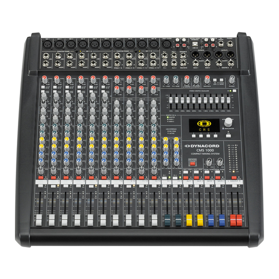
- Page 1 CMS 1000-3 | 1600-3 | 2200-3 COMPACT MIXING SYSTEM Owner‘s Manual | Bedienungsanleitung...
-
Page 3: Table Of Contents
CONTENTS INHALT ....... . 5 ........45 NTRODUCTION INFÜHRUNG Scope of Delivery, Unpacking and Inspection . - Page 4 WEEE, please contact your local distributor. We are committed to facilitate our own electronic-waste-management-system, for the free of charge return of all EVI Audio GmbH products: Telex, DYNACORD, Electro-Voice and RTS. Arrangements are made with the dealer where you purchased the...
-
Page 5: Introduction
However, if you would rather face to allow for sufficient airflow during the operation. like to install your CMS 1000-3 in a 19” rack shelf, no pro- Before establishing the mains supply connection, please blem. The only thing you have to do is to replace the make sure that the device matches the voltage and fre- plastic side panels by a pair of metal rack mount ears. -
Page 6: Controls, Indicators And Connections
2 Controls, Indicators and Connections 2.1 Input Mono HINT: When connecting signal sources, please make sure to set the corresponding channel faders or at least the master faders to their minimum positions or engage the STANDBY switch. This will save you, your audience, and the equipment from extensive wear from unpleasant pops. - Page 7 HINT: Please, do not connect E-guitars or E-basses with passive, high impedance outputs directly to a LINE input. The LINE inputs of the CMS – like the Line level inputs of mixers from other manufacturers – are designed for the connection of the relatively low source impedance of electronic instruments. The reproduction of the instrument’s original sound characteristics will be unsatisfactory.
- Page 8 5 - LO CUT 80 H When the LO CUT switch is engaged, frequencies below 80 Hz are attenuated (18 dB octave slope). In most cases using the LO CUT filter with microphone channels is a good advice, since it efficiently suppresses popping sounds, rumbling noise and low-frequency feedback.
- Page 9 7 - EQ SECTION The mixer’s EQ section allows very differentiated shaping of the incoming audio signal within miscellaneous frequency bands. Turning one of the EQ level controls to the right enhances/amplifies the corresponding frequency range while turning it to the left lowers/attenuates the signal of that specific frequency band. Before you begin to alter the sound, all EQ controls should be set to their neutral position, i.e.
- Page 10 Play the desired sound source or talk into the microphone. While doing so turn the frequency rotary control (kHz) slowly from left to right. Surely and within no time, you will detect the frequency range that is not to your liking or caus- ing the feedback.
- Page 11 HINT: Use the MUTE button for muting temporarily not used input channels without changing the settings of the FX/AUX/MON controls and the channel fader. 13 - PFL Engaging the PFL button routes the audio signal to the headphones bus, so that it is present at the phones output con- nector.
-
Page 12: Input Stereo
2.2 Input Stereo Since most features – AUX faders, controls and channel faders – of the STEREO INPUTS are virtually identical to the ones of the MONO INPUTS we will not discuss their functioning in detail again. Thus, in the following we only point out the differences and like to ask you to refer to the analogous para- graphs within this owner’s manual describing the MONO INPUTS. - Page 13 Illustration 2-11: Unbalanced or balanced assignment of phone plus UNBALANCED BALANCED SHIELD SHIELD COLD Using RCA plugs The RCA inputs CD 1-2 and CD 3-4 are connected in parallel to the phone inputs. Do not connect signal sources to phone and RCA inputs at the same time.
- Page 14 HINT: If you use a keyboard as sound source on one of the stereo inputs, make sure that no split zones or layers with channel separation are activated. The stereo channel mapping will oth- erwise appear like it is set on the keyboard – the lower layer in the left and the top layer in the right channel –...
- Page 15 23 - MON 1/2 These controls determine the amount of the summed L and R signal that is sent to the MON 1 or MON 2 summing bus. The signal gets always split pre fader. For more details on the functioning of these controls, please refer to the Input Mono section of this owner’s manual.
- Page 16 29 - FX ON/OFF Phone jack for the connection of an optionally available DYNACORD FS 11 (DC-FS11) footswitch to switch the effect mode of the internal FX units on or off. To accomplish this function, the FX 1 and FX 2 ON switches have to be engaged.
- Page 17 32 - FX 1/2 AUX 1/2 These controls allow adding the output signal (pre fader) of FX 1 or FX 2 to the AUX 1 or AUX 2 channel. 33 - FX 1/2 MON 1/2 These controls allow adding the output signal (pre fader) of FX 1 or FX 2 to the MON 1 or MON 2 channel. Experience has revealed that the effect level in the monitor mix has to be lower than the level in the master mix, since the distance between monitor speakers and artists is much shorter.
-
Page 18: Aux 1/2
2.4 AUX 1/2 Generally, the AUX 1/2 channel is used for the connection of an additional, external FX unit. De- pending on the setting of the AUX 1/2 POST button, it is also possible to configure the bus for monitoring purposes. Additionally the AUX 1/2 channels are available at the DIGITAL AUDIO IN- TERFACE. - Page 19 44 - FEEDBACK FILTER The feedback filter is a very narrow banded notch filter, which is only active in a range that is extremely susceptible for acoustical feedback. The FEEDB. FILTER rotary control sets the corresponding frequency range. Pressing the corre- sponding button activates the filter.
-
Page 20: Master With Geq
2.6 MASTER with GEQ 49 - MASTER LED DISPLAY The CMS offers two 12-segment LED-chains for opti- cal monitoring the output levels of the L/R master sig- nals. The indication range of the LED-meter is 40 dB, indicating the levels that are present at the master outputs in dBu. - Page 21 54 - MASTER A OUT L/R The mixer’s electronically balanced main outputs carrying the post master fader L/R signals for connection of the main PA. The MASTER outputs are switched via output relay with a delay of approx. two seconds after the mixer has been powered on, which prevents power-on noise when switching the mixer on or off.
- Page 22 Please make sure that the used lamp com- plies with the here mentioned specifications and pin assignment. We recommend using the gooseneck lamp (DC-LITLITE-4P), available from the DYNACORD accessory assortment. For further information, please consult your local dealer.
-
Page 23: Display With Function Keys
GEQ setting instructions: The frequency ranges as well as the characteristics of the EQ faders are very praxis-oriented. In case you want to have a clear and highly intelligible sound, which, as a side effect, provides the cymbals with more crisp, you should raise the levels of the 12 kHz or 6.3 kHz band a bit. -
Page 24: Rear Panel
HINT: The REC PEAK warning appears also when the DIGITAL AUDIO INTERFACE connected to a PC/Mac is used for playback purposes only. In this case the warning can be ignored. ACTIVE The LIMIT indicator signals that the USB connection between CMS and PC/Mac is active and the DIGITAL AUDIO INTER- FACE is ready for operation. -
Page 25: Display & Functions
3 Display & functions The CMS includes a premium OLED display. Compared to general LC displays the OLED display is brighter, has a greater contrast ratio and a wider viewing angle. 3.1 Effect mode The start screen appears after switching the CMS on. Af- Number Description ter a few seconds the default effect for FX 1 &... - Page 26 ENU STRUCTURE Illustration 3-5: Menu structure of CMS REC STUDIO MIDI PEAK AUX 1 BRIGHT HALL MONO DELAY Main Menu Large Hall 3 230 ms 40% Edit FX 1 Device Setup FX Control Setup Footswitch Ctrl. Edit FX 2 Display Brightness TAP Button Ctrl.
- Page 27 QUALIZER OUTING Parameter Description Footswitch Ctrl. Select FX 1, FX 2 or FX 1+2 to control one or both effect The 11 band Stereo Graphic Equalizer can be routed to units using a footswitch. different CMS busses. This dialog allows selecting one of TAP Button Ctrl.
- Page 28 Show Device Name EVICE ETUP This dialog can be used for editing system parameters The indication of the Device Name (instead of the status and checking system properties. Some menu entries (e.g. indications) in the top line of the display in effect mode Display Brightness) can be edited in the Device Settings can be activated or deactivated.
-
Page 29: Effects
Parameter Value USB Record Routing Live Equalizer Routing Left and right channel of master output Footswitch Ctrl. FX 1+2 TAP Button Ctrl. FX 1+2 FX 1 Start Preset FX 2 Start Preset FX 1 MIDI Channel FX 2 MIDI Channel MIDI PrgCh Count 1 - 128 Display Brightness... -
Page 30: Digital Audio Interface
For using your CMS in the Cubase software execute follo- wing steps: Start the Cubase LE software. Select Devices > Configure Devices. The Configure Devices dialog appears. Select VST-Audiosystem in the left section of the dialog. Select the ASIO driver„ASIO for DYNACORD USB- AUDIO“. -
Page 31: Status Display
HINT: For sending MIDI data from your PC to the MIDI OUT CMS, open the Sounds and Audio Devices Prop- erties in the Windows Control Panel. Select DYNACORD USB-MIDI as Default Device for MIDI to Synthesizer MIDI music playback. Vice versa, all MIDI data input via the MIDI IN jack are passed through to the PC, for instance to be recorded using a sequencer software application. -
Page 32: Examples Of Usage (Playback)
The CMS functions as an external sound card of the PC/ Device Setup Mac. In the system settings of your PC/Mac, select the CMS (DYNACORD USB-AUDIO) as the playback device. Show Device Name Audio signals are output from the PC/Mac through input... - Page 33 enhance solo vocals or a solo instrument at specific Illustration 4-9: USB Record Routing dialog (Studio) passages so that they stand clearly in front of the mix. For USB Record Routing that, you need to assign respective input channels to the AUX bus using the AUX controls.
-
Page 34: Midi Tone Generator And Multi-Effect Unit
4.7 MIDI tone generator and multi-effect unit As already explained, the CMS can be used to transfer MIDI data for instance from a master keyboard to a PC/ Mac. Using appropriate software, such as a multi-track recording application and suitable PlugIns (e.g. the sup- plied Cubase LE software), the entire world of most up- to-date sounds is always at your disposal. -
Page 35: Setting Up A Standard Pa
5 Setting up a standard PA 5.1 Cabling The mains supply cord comes with the CMS. The quality is always the better solution. Today’s modern audio of all other cables lies in your responsibility. Carefully equipment – like amplifiers, equalizers, FX units, mixing chosen high quality cables are the best precaution to pre- consoles, and even some keyboards –... -
Page 36: Setting Up
5.2 Setting up Place the CMS in a way that allows unobstructed monitor. In this case, change its position. You operation and connect the mains cord. should also be aware of the individual characteris- tics of the employed microphones. Try to locate the best position where you want to place the loudspeaker systems. - Page 37 If musical instruments are connected directly to the mon- age are necessary, activate the 11-band equalizer and aural inputs, follow the descriptions above describing the match the sound to your liking. By doing so, you should adjustment of the microphones. keep in mind, that during the performance the sound is Make sure, that all channel faders, gain and LINE CD/USB going to be altered because the audience is present,...
-
Page 38: Setup Examples
6 Setup examples 6.1 CMS with D-Lite activeone Illustration 6-1: CMS with D-Lite activeone (2 x D 8A, 1 x PowerSub 212) as main PA, 2 x D 8A used as monitors CMS 1000 COMPACT MIXING SYSTEM... -
Page 39: Cms With D-Lite Activetwo
6.2 CMS with D-Lite activetwo Illustration 6-2: CMS with D-Lite activetwo (2 x D 8A + 2 x PowerSub 112) as main PA, 2 x D 8A used as monitors CMS 1000 COMPACT MIXING SYSTEM... -
Page 40: Cms With D-Lite Activefour
6.3 CMS with D-Lite activefour Illustration 6-3: CMS with D-Lite activefour (2 x D 11A + 2 x PowerSub 212) as main PA, 2 x D 11A used as monitors CMS 1000 COMPACT MIXING SYSTEM... -
Page 41: Cms With Xa-2 System
6.4 CMS with Xa-2 system Illustration 6-4: CMS with Xa-2 system (2 x FX 12, 4 x FX20, 2 x Xa 4000) as main PA, 2 x D 8A used as monitors Xa 4000 Xa 4000 CMS 1000 COMPACT MIXING SYSTEM... -
Page 42: Cms With Corus-Evolution System
6.5 CMS with CORUS-Evolution system Illustration 6-5: CMS with CORUS-Evolution system (2 x C 25.2, 2 x Sub 2.18, 2 x LX 3000, 1 x DSP 260) as main PA, 2 x D 11A used as monitors LX 3000 LX 3000 DSP 260 CMS 1000 COMPACT MIXING SYSTEM... -
Page 43: Cms Mit Variline System
6.6 CMS mit VariLine System Illustration 6-6: CMS with VariLine system (2 x VL 152, 2 x Sub 18, 3 x LX 3000, 1 x DSP 600) as main PA, 2 x VL 122 and 1 x LX 2200 used as monitors LX 3000 LX 3000 LX 3000... - Page 44 Regelungen zur WEEE-Umsetzung in den einzelnen EU-Staaten bitten wir Sie, sich an Ihren örtlichen Händler zu wenden. Wir haben ein eigenes System zur Verarbeitung elektronischer Abfälle und gewährleisten die kostenfreie Entgegennahme aller Produkte der EVI Audio GmbH: Telex, DYNACORD, Electro-Voice und RTS. Wir haben mit dem Händler, bei dem Sie Ihr Produkt gekauft haben, eine Vereinbarung getroffen, dass alle nicht mehr verwenbaren Geräte zur umweltgerechten Entsorgung kostenfrei an das Werk...
-
Page 45: Einführung
1 Einführung 1.2 Garantie Die Compact Mixing Systeme CMS 1000-3, CMS 1600-3 und CMS 2200-3 sind professionelle Mischpulte die aufgrund der vielen integrierten Features, wie Equalizer Bewahren Sie neben der Garantiekarte auch den und Effektgeräte, eine optimierte Komplettlösung für un- terschiedlichste Einsatzgebiete darstellen. -
Page 46: Bedienelemente Und Anschlüsse
2 Bedienelemente und Anschlüsse 2.1 Input Mono HINWEIS: Achten Sie bitte darauf, dass vor dem Anschluss von Signalquellen die jeweiligen Kanalregler, mindestens jedoch die beiden Masterregler, geschlossen sind, oder der STANDBY-Schalter gedrückt ist. Sie ersparen sich selbst, Ihrem Publikum und Ihrem Equipment unnötige Beanspruchungen durch Knackgeräusche. - Page 47 HINWEIS: Betreiben Sie bitte keine E-Gitarre bzw. E-Bass mit passiver Elektronik und hochohmigem Ausgang direkt an einem Mischpult Line-Eingang. Diese Eingänge sind typischerweise, auch bei allen andern Herstellern, für relativ niedrige Quellimpedanzen ausgelegt, wie sie elektronische Geräte aufweisen. Das Klangergebnis wird unbefriedigend sein und der Klangcharakteristik der Instrumente nicht gerecht werden.
- Page 48 5 - LO CUT 80 H CHALTER Mit dem LO CUT 80 Hz-Schalter können Bassfrequenzen unterhalb 80 Hz mit einer Flankensteilheit von 18 dB pro Oktave unterdrückt werden. Sinnvoll ist die Benutzung des LO CUT-Filters bei allen Mikro- fonanwendungen, wobei hier die Abnahme von Bassdrum oder Bass gesondert zu betrachten ist. Mit diesem Filter werden wirkungsvoll alle Rumpel- oder Poppgeräusche als auch tieffrequente Feedback- signale unterdrückt.
- Page 49 7 - K (HI-, MID-, LO-R LANGREGELUNG EGLER Die Klangregelung erlaubt eine sehr umfangreiche und effektive Beeinflussung des Eingangssignals innerhalb unter- schiedlicher Frequenzbereiche. Eine Drehung der Klangregler nach rechts bewirkt eine Anhebung/Verstärkung des ent- sprechenden Frequenzbereichs. Eine Drehung nach links bewirkt eine Absenkung/Abschwächung des entsprechenden Frequenzbereichs.
- Page 50 zurück. Weiter Informationen finden Sie in den Abschnitten EFFEKT 1/2. Wenn Sie die eingebauten Effekteile nicht, bzw. zusätzliche externe Effektgeräte benutzen wollen, steht das jeweilige FX- Summensignal auch im Masterbereich an den FX 1/2-Buchsen zur Verfügung. 9 - AUX 1/2-R EGLER Die AUX 1- bzw.
- Page 51 14 - SIG/PK-A NZEIGE Die Signal / Peak-Anzeige hat eine Schlüsselfunktion bei der Pegelkontrolle im Betrieb. Durch Aufleuchten der PK-LED (Peak) sehen Sie bereits wenn Übersteuerungsgefahr besteht und müssen die Verzerrung nicht erst akustisch wahrnehmen. Wie bereits in den Einstellhinweisen (Seite 47) beschrieben, sollte die SIG-LED (Signal) rhythmisch dem eingespielten Signal folgen.
-
Page 52: Input Stereo
2.2 Input Stereo Wir wollen Sie hier bei der Beschreibung des STEREO-INPUTS nicht langweilen, viele Funktionsgrup- pen wie AUX-Regler, MON-Regler, Kanalfader sind im STEREO INPUT identisch zum MONO INPUT aufgebaut und wurden dort bereits ausführlich erklärt. Wir wollen hier nur die wesentlichen Unter- schiede herausarbeiten. - Page 53 Abbildung 2-10: Unsymmetrische bzw. symmetrische Belegung von Klinkensteckern UNBALANCED BALANCED SHIELD SHIELD COLD Verwendung von Cinch-Steckern Die Cinch-Eingänge CD 1-2 und CD 3-4 sind den Klinken-Eingängen parallel geschaltet. Um gegenseitige Beeinflussung zu vermeiden sollte nur an den Cinch- oder den Klinken-Eingängen eine Quelle eingesteckt sein. Abbildung 2-11: Cinch-Eingangsbuchsen Je nach Gerätevariante sind die Eingänge CD 1-2 bzw.
- Page 54 19 - GAIN LINE CD / USB-R EGLER Mit diesem Regler wird das Signal an den Line-Eingängen bzw. Cinch-/USB-Eingängen im Stereokanal an den internen Arbeitspegel des Mischpultes angepasst. Der Regelbereich liegt bei 30 dB. Die Unity- Gain-Position, also 0 dB Durchgangsverstärkung, ist hier bei der Markierung 0 dB. Sie können mit die- sem Regler das Signal um bis zu 10 dB abschwächen bzw.
- Page 55 23 - MON 1/2-R EGLER Mit diesen Reglern wird das aus dem linken und rechten Kanal summierte Signal PRE-FADER auf die MON 1- bzw. MON 2-Summenschienen ausgespielt. Die Funktionsweise wurde bereits im Abschnitt Input Mono erläutert. 24 - BAL-R EGLER Ähnlich wie beim Panorama-Regler im Monokanal, wird hier die Balance des Signals im Stereobild angepasst.
- Page 56 Die Klinkenbuchse FX ON/OFF dient zum Anschluss eines Fußschalters FS 11 (DC-FS11) aus dem Zu- behörprogramm von DYNACORD. Die eingebauten Effektteile können damit ein- und ausgeschaltet werden. Zur Fernsteuerung mittels Fußschalter müssen die Effektgeräte über die FX 1 ON- bzw. FX 2 ON-Schalter im Effektkanal aktiviert sein.
- Page 57 30 - FX 1/2 SENDS-B UCHSEN An der Buchse FX 1 bzw. FX 2 steht die Abmischung, die Sie über die jeweilige FX-Schiene erstellt haben, parallel zum Effektteil zur Verfügung. Sie können hier z. B. ein externes Effektgerät anschließen. Das extern erzeugte Effektsignal kann dann über einen Stereo-Input zurückgeführt werden.
-
Page 58: Aux 1/2
2.4 AUX 1/2 Die Kanalzüge AUX 1/AUX 2 können beliebig zum Monitoring oder als zusätzliche FX Sends (bei gedrückter AUX 1/2 POST Taste) betrieben werden. Zusätzlich sind AUX 1 bzw. AUX 2 auf den Ka- nälen USB 3 bzw. USB 4 des DIGITAL AUDIO INTERFACE verfügbar. 38 - AUX 1/2 SENDS-B UCHSEN Hier schließen Sie entweder ein Effektgerät oder im Monitorbetrieb eine Monitorendstufe bzw. - Page 59 Terz- oder Oktavequalizer, Kompressor, Limiter, De-Esser, usw. in den MON-Kanal. Der Einschleifpunkt liegt schaltungs- technisch vor den MON-Fadern. Hier sind, wie auch bei den Inserts in den Monokanälen, verschiedene DIRECT OUT Funktionen möglich. Beachten Sie hierzu den entsprechenden Abschnitt auf Seite 47. 44 - FEEDBACK FILTER-S CHALTER Das Feedback-Filter ist ein spezielles Notch-Filter zur schmalbandigen Unterdrückung eines rückkopplungs-...
-
Page 60: Master Mit Geq
2.6 MASTER mit GEQ 49 - MASTER LED-D ISPLAY Die Aussteuerungsanzeige im CMS besteht aus zwei LED-Ketten für den rechten bzw. linken Kanal mit je 12 LEDs pro Kette. Der Anzeigebereich liegt bei 40 dB und stellt den Pegel in dBu an den Master Outputs dar. - Page 61 54 - MASTER A OUT L/R-B UCHSEN Dies sind die elektronisch symmetrischen Hauptausgänge des Mixers, die nach den Masterfader L/R angeordnet sind. Hier wird die Haupt-Beschallungsanlange angeschlossen. Die MASTER Ausgänge sind mit Ausgangsrelais ausgestattet, durch die Knackgeräusche beim Ein- bzw. Ausschalten des Gerätes unterdrückt werden. Bitte beachten Sie, dass das Mastersignal erst ca.
- Page 62 Lampe. Der Ausgang ist vor Kurzschluss und Überlas- tung geschützt. Sollte die angeschlossene Lampe nicht leuchten, überprüfen Sie bitte das Leuchtmittel und die Pinbelegung des XLR-Steckers. Verwenden Sie möglichst nur die Schwanenhals-Lampe (DC-LIT- LITE-4P) aus dem DYNACORD-Zubehörprogramm. Fragen Sie bei Ihrem Fachhändler nach.
-
Page 63: Display Mit Funktions-Tasten
Abbildung 2-17: Belegung der LAMP 12V/5W-Buchse 67 - 11-BAND STEREO GRAPHIC EQUALIZER In den Masterkanal (oder wahlweise in die Monitorkanäle) kann ein 11-Band Equalizer über die ON-Taste eingeschaltet werden. Der EQ liegt dann schaltungstechnisch nach den Master-Schiebereglern und vor den MASTER A OUT L/R-Buch- sen. - Page 64 Effekt-Betriebsart Das Display zeigt in der Effekt-Betriebsart die aktuell eingestellte Programmnummer des jeweiligen Effektteils an. Mit den vier Tasten unter dem Display werden die Effektprogramme angewählt. Weitere Informationen finden Sie im Abschnitt “Effekt-Betriebsart” auf Seite 66. Menü-Betriebsart Durch Drücken des MENU/ENTER-Drehencoders wechselt die Anzeige von der Effekt-Betriebsart in die Menü-Betriebs- art.
-
Page 65: Rückseite
2.8 Rückseite 73 - N ETZBUCHSE Die Spannungsversorgung des CMS erfolgt ausschließlich mit dem mitgelieferten IEC-Netzkabel über eine verriegelnde Netzbuchse. Schließen Sie das CMS nur an eine geeignete Netzversorgung an, die den auf dem Typenschild angegebenen Anforderungen entspricht. HINWEIS: Zum Abziehen des Netzkabels drücken Sie die gelbe Entriegelung-Taste am Stecker. 74 - N (POWER) ETZSCHALTER... -
Page 66: Display & Funktionen
3 Display & Funktionen Das CMS ist mit einem hochwertigen OLED-Display ausgestattet. Im Vergleich zu üblichen LC-Displays sind OLED-Dis- plays wesentlich heller, kontrastreicher und sind unabhängig vom Blickwinkel optimal abzulesen. 3.1 Effekt-Betriebsart Nach dem Einschalten des CMS wird der Startbildschirm Nummer Beschreibung angezeigt. - Page 67 ENÜ Abbildung 3-5: Menüstruktur des CMS REC STUDIO MIDI PEAK AUX 1 BRIGHT HALL MONO DELAY Main Menu Large Hall 3 230 ms 40% Edit FX 1 Device Setup FX Control Setup Footswitch Ctrl. Edit FX 2 Display Brightness TAP Button Ctrl. USB Record Routing Screensaver FX1 Start Preset...
- Page 68 MENU/ENTER-Drehencoders übernimmt die gewählte Zu- Parameter Beschreibung ordnung. Drücken der BACK-Funktionstaste führt in das Footswitch Ctrl. Ein angeschlossener Fußschalter kann für die Bedienung Menü zurück. Drücken der ESC-Funktionstaste führt in eines einzelnen oder beider Effektteile verwendet wer- die Effekt-Betriebsart zurück. den.
- Page 69 Abbildung 3-13: FX Control Setup nach links, um die Zeit bis zur Aktivierung zu verkürzen bzw. den Bildschirmschoner zu deaktivieren (Off). FX Control Setup Drehen Sie den MENU/ENTER-Drehencoder nach rechts, um die Zeit bis zur Aktivierung zu verlängern. Drücken des Footswitch Ctrl.
-
Page 70: Effekte
ders zwischen YES und NO gewählten werden. Bei Wahl Parameter Wert von YES werden durch den Rücksetzvorgang auch alle USB Record Routing Live vorhandenen FX User Presets gelöscht. Bei Wahl von NO Equalizer Routing Linker und rechter Kanal des Master-Ausgangs werden die vorhandenen FX User Presets nicht gelöscht. -
Page 71: Digital Audio Interface
Audiosystem. aus. Wählen Sie als ASIO-Treiber den Eintrag „ASIO for Wählen Sie im Startbildschirm die gewünschte DYNACORD USB-AUDIO“. Sprache für die Anwendung aus. Schließen Sie den Dialog durch Klick auf OK. Starten Sie die Installation durch Klick auf „Install HINWEIS: Informationen zur Verwendung von Cubase Cubase LE“... -
Page 72: Funktionsanzeige Im Display
4.4 PC-MIDI-Interface Das CMS stellt Ihnen ein vollwertiges PC-MIDI-Interface Beachten Sie, dass auch Steuerdaten für die eingebauten zur Verfügung. Der im PC/Mac als DYNACORD USB-MIDI Effektteile, die Sie z. B. über einen MIDI-Fußschalter bezeichnete Port kann überall ausgewählt werden, wo fernbedienen, an den PC übermittelt werden. -
Page 73: Anwendungsbeispiele (Wiedergabe)
Sollen MIDI-Daten mit der Medienwiedergabe von Windows an externen Geräten wiedergegeben wer- den, müssen Sie in der Windows-Systemsteuerung den Dialog "Sounds und Audiogeräte" öffnen und das Standardgerät der MIDI-Musikwiedergabe auf DYNACORD USB-MIDI umstellen. 4.5 Anwendungsbeispiele (Wiedergabe) der Ausspielwege auf die Wiedergabekanäle des CMS... -
Page 74: Anwendungsbeispiele (Aufnahme)
Auf diese Weise wird einer Klangverfälschung vor- gebeugt, die entstehen könnte, wenn das USB-Signal über die Stereofader und gleichzeitig den 2TRACK IN- Regler auf den Master gelangen würde. 4.6 Anwendungsbeispiele (Aufnahme) Bei den folgenden Anwendungen wird Ihr PC/Mac zur HINWEIS: Beachten Sie, dass bei der Aufnahme die Aufnahme verwendet, das CMS fungiert hierbei als hoch- Signale der Raummikrofone nicht in die... -
Page 75: Midi-Klangerzeuger Und Multieffektgerät
Fader des Mischpultes dazu verwenden, die Monito- wieder zum Mischpult zurückgeleitet werden muss. Letz- rabmischung für die Musiker zu erstellen. Für das Monito- teres ist prinzipbedingt immer mit einer gewissen Durch- ring sollten Sie selbstverständlich Kopfhörer verwenden, laufverzögerung (Latenz) verbunden. da Lautsprecher auch immer auf die Aufnahmemikrofone einwirken. -
Page 76: Aufbau Einer Standard-Pa
5 Aufbau einer Standard-PA 5.1 Verkabelung Das Netzkabel haben Sie mit dem CMS erhalten. Für alle meisten Audiogeräte wie Endstufen, Equalizer, Effekt- anderen Kabel sind Sie selbst verantwortlich und je sorg- geräte, Mischpulte und auch einige Keyboards verfügen fältiger Sie bei der Auswahl der Kabel vorgehen, um so über symmetrisch aufgebaute Eingänge bzw. -
Page 77: Aufbau
5.2 Aufbau Stellen Sie das CMS so auf, dass Sie auch im darauf, dass nicht eines der Mikrofone direkt auf Betrieb leichten Zugriff haben und schließen Sie die die Monitore zielt. Beachten Sie auch die Charakte- Netzkabel an. ristik der verwendeten Mikrofone. Suchen Sie die günstigste Position für Ihre PA- Verkabeln Sie die Bassboxen, Monitorboxen und Boxen. - Page 78 Überprüfen Sie nun, ob bei allen nicht benötigten ETZTE ORREKTUREN Eingängen die Kanalfader und die GAIN-, GAIN MIC-, LINE CD- bzw. LINE USB-Regler geschlossen sind. Sie ver- Spielen Sie nun im komplett Setup und hören Sie die meiden dadurch unnötiges Rauschen auf den Ausgängen. Haupt-PA aus verschiedenen Entfernungen ab.
-
Page 79: Aufbaubeispiele
6 Aufbaubeispiele 6.1 CMS mit D-Lite activeone Abbildung 6-1: CMS mit D-Lite activeone (2 x D 8A, 1 x PowerSub 212) als Haupt-PA, zusätzlich 2 x D 8A für die Monitorwege CMS 1000 COMPACT MIXING SYSTEM... -
Page 80: Cms Mit D-Lite Activetwo
6.2 CMS mit D-Lite activetwo Abbildung 6-2: CMS mit D-Lite activetwo (2 x D 8A + 2 x PowerSub 112) als Haupt-PA, zusätzlich 2 x D 8A für die Monitorwege CMS 1000 COMPACT MIXING SYSTEM... -
Page 81: Cms Mit D-Lite Activefour
6.3 CMS mit D-Lite activefour Abbildung 6-3: CMS mit D-Lite activefour (2 x D 11A + 2 x PowerSub 212) als Haupt-PA, zusätzlich 2 x D 11A für die Monitorwege CMS 1000 COMPACT MIXING SYSTEM... -
Page 82: Cms Mit Xa-2 System
6.4 CMS mit Xa-2 System Abbildung 6-4: CMS mit Xa-2 System (2 x FX 12, 4 x FX20, 2 x Xa 4000) als Haupt-PA, zusätzlich 2 x D 8A für die Monitorwege Xa 4000 Xa 4000 CMS 1000 COMPACT MIXING SYSTEM... -
Page 83: Cms Mit Corus-Evolution System
6.5 CMS mit CORUS-Evolution System Abbildung 6-5: CMS mit CORUS-Evolution System (2 x C 25.2, 2 x Sub 2.18, 2 x LX 3000, 1 x DSP 260) als Haupt-PA, zusätzlich 2 x D 11A für die Monitorwege LX 3000 LX 3000 DSP 260 CMS 1000 COMPACT MIXING SYSTEM... -
Page 84: Cms Mit Variline System
6.6 CMS mit VariLine System Abbildung 6-6: CMS mit VariLine System (2 x VL 152, 2 x Sub 18, 3 x LX 3000, 1 x DSP 600) als Haupt-PA, zusätzlich 2 x VL 122 und 1 x LX 2200 für die Monitorwege LX 3000 LX 3000 LX 3000... -
Page 85: Specifications
7 Specifications Property CMS 1000 CMS 1600 CMS 2200 Order No. F01U138112 F01U138114 F01U138115 DC-CMS1000-3-UNIV DC-CMS1600-3-UNIV DC-CMS2200-3-UNIV Channels (Mono + Stereo) 6 + 4 12 + 4 18 + 4 Auxiliarys (MON, FX, AUX) 2 Pre, 2 Post, 2 Pre/Post switchable MIC GAIN (Mono) 0 to +60 dB MIC GAIN (Stereo) - Page 86 Property CMS 1000 CMS 1600 CMS 2200 Display 128 x 64 pixels, OLED Digital Audio Interface Channels 4 In / 4 Out AD/DA Conversion 24-bit Sampling Rate 44.1 / 48 / 88.2 / 96 kHz PC Interface USB2.0, Female Type B Peak Display 6 dB before Clip MIDI Interface...
-
Page 87: Dimensions
7.1 Dimensions... -
Page 88: Block Diagram
7.2 Block Diagram... - Page 89 Trademarks. • Microsoft, Windows, Windows XP, Windows Vista and Windows 7 are either registered trademarks or trademarks of Microsoft Corporation in the United States and/or other countries • Apple, Macintosh, Mac OS and Mac OS X are trademarks of Apple Inc., registered in the United States and other countries •...
- Page 90 Notes...
- Page 91 Notes...
- Page 92 DYNACORD 12000 Portland Avenue South, Burnsville, MN 55337, USA Europe, Africa, and Middle East only. For customer orders, contact Customer Service at: Phone: +1 952/844-4051, Fax: +1 952/884-0043 +49 9421-706 0 Fax: +49 9421-706 265 Asia & Pacific only. For customer orders, contact Customer Service at: www.dynacord.com...
Need help?
Do you have a question about the CMS 1000-3 and is the answer not in the manual?
Questions and answers