Table of Contents
Advertisement
Quick Links
DIY
Series
®
Outtasight
One-Way Cassette
Installation &
Owner's Manual
MODELS:
DIYCASSETTE*HP-230D25-O
Read this manual carefully before installation and keep it where
the operator can easily find it for future reference.
Due to updates and constantly improving performance, the
information and instructions within this manual are subject to
change without notice.
Version Date: January 27, 2025
Please visit www.mrcool.com/documentation
to ensure you have the latest version of this manual.
TM
Advertisement
Table of Contents

Related Manuals for MrCool DIY Outtasight DIYCASSETTEHP-230D25-O Series


Summary of Contents for MrCool DIY Outtasight DIYCASSETTEHP-230D25-O Series
- Page 1 Due to updates and constantly improving performance, the information and instructions within this manual are subject to change without notice. Version Date: January 27, 2025 Please visit www.mrcool.com/documentation to ensure you have the latest version of this manual.
-
Page 2: Table Of Contents
................27 ELECTRICAL CONNECTIONS ..................36 POST-INSTALLATION ...................... 38 8.1 Electrical & Gas Leak Checks ................38 8.2 Test Run ....................... 39 8.3 Packing & Unpacking the Unit ................40 8.4 Care & Maintenance ................... 40 8.5 Troubleshooting ....................43 mrcool.com... -
Page 3: Safety Precautions
The unit’s circuit board (PCB) is designed with a fuse to provide over-current protection. • The specifications of the fuse are printed on the circuit board, examples of such are T3.15AL/250VAC, T5AL/250VAC, T3.15A/250VAC, T5A/250VAC, T20A/250VAC, T30A/250VAC Note: Only a blast-proof ceramic fuse can be used. mrcool.com... - Page 4 Call your local dealer, or MRCOOL® tech support at (270) 366-0457, for further assistance. 2. If the air conditioner is used together with burners or other heating devices, thoroughly ventilate the room in order to avoid an oxygen deficiency.
- Page 5 The service life of the refrigerant sensor is 15 years. When the refrigerant sensor malfunctions, the indoor unit will display the error code "FHCC". The refrigerant sensor cannot be repaired and can only be replaced with a sensor approved by MRCOOL ®...
- Page 6 mrcool.com...
- Page 7 When the final oxygen-free nitrogen charge is used, the system should be vented down to atmospheric pressure to enable work to take place. The outlet for the vacuum pump should not be close to any potential ignition sources, and ventilation should be available. mrcool.com...
- Page 8 The recovered refrigerant should be processed according to local legislation in the correct recovery cylinder, and the relevant waste transfer note arranged. Do not mix refrigerants in recovery units and especially not in cylinders. mrcool.com...
- Page 9 0.25 times the maximum allowable pressure. No leak should be detected. • Any servicing should be performed only as recommended by MRCOOL®. 44. Any maintenance, service, or repair operations must be performed by qualified personnel. Every working procedure that affects safety should only be carried out by competent persons that are both trained and certified.
-
Page 10: Unit Overview
Parts must be purchased after wiring and Φ1/4in (Φ6.35mm) Φ3/8in (Φ9.52mm) Connecting Pipe separately. Consult your dealer or piping have been technician about the proper pipe Assembly Φ1/4in (Φ6.35mm) Φ3/8in (Φ9.52mm) completed. size for the unit you purchased. Φ1/4in (Φ6.35mm) Φ1/2in (Φ12.7mm) mrcool.com... -
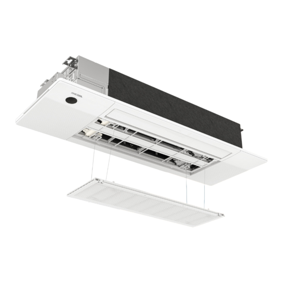
Page 11: Product Overview
1. Display Panel 5. Air Inlet (w/ air filter) 10. Refrigerant Piping 2. Circuit Breaker 6. Air Outlet (Airflow Louver) 11. Outdoor Unit Power Cable 3. Installation Bracket 7. Remote Control 12. Outdoor Unit 4. Drain Pipe 8. Remote Control Holder mrcool.com... -
Page 12: Unit Parts
When pre-heating/defrost feature is activated. Displays temperature, operation features, & error codes. When 46°F/8°C heating feature is turned on. When active clean feature is turned on. When wireless module enters AP mode. When forced cooling feature is turned on. mrcool.com... -
Page 13: Operating Features
For some units, the system will start a high manual processing. temperature cleaning process, and the temperature of the air outlet is very high, leading to higher room temperature. Stay away during this process. mrcool.com... -
Page 14: Indoor Unit Installation
ǿ Areas with caustic gases in the air, such as hot springs. ǿ Areas that store flammable materials or gas. ǿ Areas that experience power fluctuations, such as ǿ Rooms with high humidity, such as bathrooms factories. or laundry rooms. ǿ Enclosed spaces, such as cabinets. mrcool.com... - Page 15 WARNING The minimum room area or minimum room area of conditioned space is based on releasable charge and total system refrigerant charge. mrcool.com...
- Page 16 Indoor Normal Air Volume DIYCASSETTE06HP-230D25-O DIY-MULTI3-18HP230D-O 540m 318CFM DIY-MULTI4-27HP230D-O DIY-MULTI5-36HP230D-O DIY-MULTI6-48HP230D-O DIY-MULTI6-55HP230D-O DIYCASSETTE09HP-230D25-O DIY-MULTI3-18HP230D-O 540m 318CFM DIY-MULTI4-27HP230D-O DIY-MULTI5-36HP230D-O DIY-MULTI6-48HP230D-O DIY-MULTI6-55HP230D-O DIYCASSETTE12HP-230D25-O DIYHH-12-HP-C-230D25-O 800m 470CFM DIY-MULTI3-18HP230D-O DIY-MULTI4-27HP230D-O DIY-MULTI5-36HP230D-O DIY-MULTI6-48HP230D-O DIY-MULTI6-55HP230D-O DIYCASSETTE18HP-230D25-O DIYHH-18-HP-C-230D25-O 1000m 588CFM DIY-18-HP-C-230D25-O DIY-MULTI3-18HP230D-O DIY-MULTI4-27HP230D-O DIY-MULTI5-36HP230D-O DIY-MULTI6-48HP230D-O DIY-MULTI6-55HP230D-O mrcool.com...
-
Page 17: Installation Dimensions
INDOOR UNIT INSTALLATION 3.2 Installation Dimensions Installation Location Dimensions Refer to the cardboard template for correct dimensions of the ceiling hole. Parts Installation Size mrcool.com... -
Page 18: Installation Steps
Step 2: WARNING Remove the pre-cutting cover on the circuit breaker box. The ground wire should be tightened firmly without loosening. Step 4: Fasten and fix the wire body with a tie. mrcool.com... - Page 19 NOTE Be sure to reserve a length of the connecting wire for periodic maintenance. If there is a connection lug at the end of the shielded wire, the connection lug should be properly grounded. mrcool.com...
-
Page 20: Outdoor Unit Installation
ǿ Near a public street, crowded areas, or where noise from the unit will disturb others. ǿ Near any source of combustible gas. ǿ In a location exposed to excessive amounts of salty air. ǿ In a location exposed to large amounts of dust. mrcool.com... -
Page 21: Install Drain Joint
Connect a drain hose extension (not included) to the drain joint to redirect water from the unit during heating mode. NOTE: In cold climates, ensure that the drain hose is as vertical as possible to ensure swift water drainage. If water drains too slowly, it can freeze in the hose and flood the unit. mrcool.com... -
Page 22: Anchor Outdoor Unit
9.8in (250mm) or more L ≤ H 1/2H < L ≤ H 11.8in (300mm) or more L > H Cannot be installed Note: H: Unit Height L: Height of the Wall Behind the Unit A: Distance Between Unit and Wall mrcool.com... -
Page 23: Drainpipe Installation
DO NOT pull the drainpipe forcefully. This could disconnect it. • Drainpipe installation should comply with all local and national codes and regulations. • Note: Installation requires 3/4in PVC pipe, which can be obtained at your local hardware store or dealer. mrcool.com... - Page 24 11.8in (30cm). Incorrect installation could cause water to flow back into the unit and flood. • To prevent air bubbles, keep the drain hose level or slightly tiled up (< 3in/75mm). mrcool.com...
- Page 25 U or S pipe to catch odors that might otherwise come back into the house. NOTE: When the gas side connective pipe is Φ5/8in (16mm) or more, the wall hole should be 3.54in (90mm). mrcool.com...
-
Page 26: Panel Installation
NOTE: The corresponding colors or corresponding pins cassette panel to the one-way cassette with the are connected to each other. two plastic buckles. 3. Manually rotate the air deflector, and fix the panel to the cassette using 3xM4*22 screws and a ST3.9*16 screw. mrcool.com... - Page 27 Note: If you choose this configuration, it is recommended to install the smart controller during the panel installation 1. Remove the protective cap of the smart controller. Install the smart controller with the vent (circled above) facing outward to allow for sufficient airflow. mrcool.com...
-
Page 28: Refrigerant Piping Connection
3. Pack the wall hole with the supplied Neoprene (or Spray Foam can be used) to seal the hole, filling any space that was not taken up by the refrigerant piping and lines. mrcool.com... - Page 29 DO NOT remove the sealing caps and stoppers from the line set or valves until immediately before IMPORTANT: Before you continue, it is essential that they are to be connected. you read the following instructions fully and carefully. • DO NOT smoke during the installation. mrcool.com...
- Page 30 (based on pipe/coupling size). *If an HVAC torque wrench is NOT available: Using two wrenches you used to tighten the connector, once the connector is snug, turn the wrench slightly beyond that point to torque the connector, but do not overtighten it. mrcool.com...
- Page 31 This will also of the outdoor unit, tightening the first few threads by void the warranty. hand. NOTE: Keep excess refrigerant hose coiled. Wrap with protective tape and store behind the condenser in a horizontal position (flat with the ground). mrcool.com...
- Page 32 DO NOT force it. Screw the cover onto the ensure that it is properly sealed. bottom valve and tighten it well to ensure that it is properly sealed. CAUTION If the valves are not fully opened, it could cause the system to malfunction and suffer damage. mrcool.com...
- Page 33 DO NOT wrap the end of the drain hose. 2. Now, place the supplied insulation material over the connectors and exposed refrigerant piping. 4. Finally, fix the water receiver (supplied in the accessories box) to the indoor unit with a screw. mrcool.com...
- Page 34 This will encase your refrigerant piping and lines, protecting them from harsh weather conditions and sun exposure, which will extend the life of your system. These covers are available in various sizes to fit your particular application. mrcool.com...
- Page 35 DO NOT put the end of the drain hose in water or a container that will collect water. ENSURE UNUSED DRAIN HOLE IS PLUGGED To prevent unwanted leaks, be sure that the factory- installed hollow center rubber plug is installed in the unused drain hole. mrcool.com...
- Page 36 10. If the unit has an auxiliary electric heater, it must be installed at least 40in (1m) away from combustible materials. 11. To avoid electrical shock, never touch the electrical components soon after the power supply has been turned off. Always wait 10 minutes or more before touching the electrical components once the power has been turned off. mrcool.com...
-
Page 37: Electrical Connections
All wiring must be performed in accordance with below. the wiring diagrams shown here. WIRES AND TERMINALS ARE NUMBERED TO CORRESPOND WITH ONE ANOTHER AS SHOWN BELOW. NOTICE: Refer to the wiring diagram in the manual of the outdoor unit for multi-zone system models. mrcool.com... - Page 38 4. Now, secure the DIYPRO® cable to the electrical cover by pushing the threaded end of the cable into the hole and reinstalling the retaining nut previously removed onto the end of the cable. Refer to the following images. mrcool.com...
-
Page 39: Post-Installation
The presence of bubbles indicates there is a leak. Leak Detector Method - If using a leak detector, refer to the device's operation/instruction manual for proper usage instructions. mrcool.com... -
Page 40: Test Run
Make sure there is no vibration or abnormal noise during operation. c. Ensure the wind, noise, and water generated by the unit do not disturb your neighbors or pose a safety hazard. mrcool.com... -
Page 41: Packing & Unpacking The Unit
Do not use water hotter than 104°F (40°C) to clean the front panel. This can cause the panel to deform or become discolored. • Do not wash the unit under running water. Doing so creates an electrical hazard. Clean the lint using a damp, lint-free cloth and neutral detergent. Dry the unit with a dry, lint-free cloth. mrcool.com... - Page 42 • Do not pull the wire rope. If necessary, contact 5. Move the filter to the right until it is separated customer service. from the air grille, and then the filter can be taken out. mrcool.com...
-
Page 43: Maintaining The Unit
Clean all filters. Clean all filters. until unit dries out wires. completely. Check for leaks. Replace batteries. Turn off the unit & Remove batteries disconnect the power. from remote control. Ensure nothing is blocking the air inlets & outlets. mrcool.com... -
Page 44: Troubleshooting
The fan of the outdoor unit During operation, the fan speed is controlled to optimize product operation. does not operate. MRCOOL® Note: If a problem persists, contact a local dealer or customer service. Provide them with a detailed description of the unit malfunction as well as your model number. - Page 45 E(x), P(x), F(x), EH(xx), EL(xx), EC(xx), PH(xx), PL(xx), PC(xx) Note: If your problem persists after performing the checks and diagnostics above, turn off your unit immediately and contact a local dealer or MRCOOL® customer service. mrcool.com...
-
Page 46: Error Display (Indoor Unit)
Test the unit using the remote control. If the unit does undefined by the service manual. Ensure that this not respond to the remote, the indoor PCB requires code is not a temperature reading. replacement. If the unit responds, the display board requires replacement. mrcool.com... -
Page 47: Remote Maintenance
Compressor short-cycles due to overload TS16-TS17 High discharge pressure TS16-TS17 Low discharge pressure TS16-TS17 High suction presure TS16-TS17 Low suction pressure TS16-TS17 Unit runs continuously but insufficient cooling TS16-TS17 Too cool TS16-TS17 Compressor is noisy TS16-TS17 Horizontal louver cannot revolve TS16-TS17 mrcool.com... - Page 48 Series ® Outtasight One-Way Cassette The design and specifications of this product and/or manual are subject to change without prior notice. Consult with the sales agency or manufacturer for details.
Need help?
Do you have a question about the DIY Outtasight DIYCASSETTEHP-230D25-O Series and is the answer not in the manual?
Questions and answers