Table of Contents
Advertisement
Advertisement
Table of Contents

Subscribe to Our Youtube Channel
Related Manuals for Marmitek IP EYE ANYWHERE 10 - ADVANCED


Summary of Contents for Marmitek IP EYE ANYWHERE 10 - ADVANCED
-
Page 2: Table Of Contents
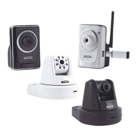
REFACE Thank you for purchasing the Marmitek Wireless* Pan-Tilt** MPEG4/MJPEG*** Network Camera, a powerful dual-codec*** wireless* network camera with the 1-way**** or 2-way***** audio function that provides the high-quality image and on-the-spot audio via the Internet connection. The Infrared LEDs and light sensor *****enable the camera to capture images even in the dark environment. - Page 3 NOTE The illustrations and configuration values in this guide are for reference only. The actual settings depend on your practical application of the camera. © MARMITEK...
-
Page 4: H A P T E
ONTENTS ................0 P r e f a c e . -
Page 5: Safety Warnings
Marmitek does not accept responsibility in the case of improper usage of the product or when the product is used for purposes other than specified. Marmitek does not accept responsibility for additional damage other than covered by the legal product responsibility. -
Page 6: Ip Eye Anywhere 11, 21, Ip Robocam
HAPTER NTRODUCTION AMERA Checking the Package Contents Check the items contained in the package carefully. You should have the following: One Network Camera. One AC Power Adapter. One External Antenna.* One Wall Mount Kit. One GPIO Connector** One Ethernet Cable (RJ-45 type). One Installation CD-ROM. -
Page 7: Getting To Know Your Camera
Lens Assembly USB Port*** allows you to connect an external USB device. It provides the power distribution up to 500mA. USB*** Unmount Button Is used to remove the connected USB device safely. Front view IP Eye Anywhere © MARMITEK... - Page 8 Light Sensor ***** is used to trigger on and off the Infrared LEDs according Antenna* the environmental light level. Infrared LEDs (x7)***** allow your camera to capture clear image in a dark environment. Lens Assembly Power LED indicates the camera is powered on with the steady amber light.
- Page 9 Reset Button will restart to the camera. network speed automatically. the camera when it is pressed quickly; when it is long pressed for five seconds, the camera will resume the factory default settings. Rear View IP Eye AnyWhere © MARMITEK...
- Page 10 Ethernet Cable Connector connects the network cable, which supports the NWay protocol so that the External Antenna camera can detect the Connector* connects network speed the external antenna. automatically. DC Power Connector connects the AC power adapter, in order to supply power to the camera.
-
Page 11: Features And Benefits
„ Day & Night Surveillance Supported***** The seven Infrared LEDs around the standard lens assembly enable the Marmitek IP RoboCam 21 to capture crystal clear images in the dark environment or at night. When the Light Sensor detects the environmental light level becomes low, the camera captures the images in black &... - Page 12 MJPEG, and 3GPP. „ I/O Connectors Provided** The Marmitek IP RoboCam camera provides the I/O connectors on the rear panel (IN/OUT), which provide the physical interface to send and receive digital signals to a variety of external alarm devices. You...
-
Page 13: System Requirement
5 ~ 8 cameras connected: Intel Pentium 4 2.4GHz; 1GB RAM 9 ~ 16 cameras connected: Intel Pentium 4 3.4GHz; 2GB RAM Resolution: 1024x768 or above NOTE If you connect multiple cameras to monitor various places simultaneously, you are recommended to use a computer with higher performance. © MARMITEK... -
Page 14: Hardware Installation
NSTALLATION Installing the Camera Stand, Wall Mount The Marmitek IP Eye Anywhere camera comes with a camera stand, which uses a swivel ball screw head to lock to the camera’s screw hole. When the camera stand is attached, you can place the camera anywhere by mounting the camera through the three screw holes located in the base of the camera stand. - Page 15 The Marmitek IP RoboCam camera comes with a Wall Mount Kit, which allows you to place your camera anywhere by mounting the camera through the three screw holes located in the base of the Wall Mount Kit. Screw Wall Mount Kit...
-
Page 16: Connecting Thec
Connecting the Camera to LAN/WLAN Use the provided Ethernet cable to connect the camera to your local area network (LAN). When you connect the AC power adapter, the camera is powered on automatically. You can verify the power status from the Power LED on the front panel of the camera. -
Page 17: Applications Of The Camera
„ Upload images or send email messages with the still images attached. The following diagram explains one of the typical applications for your camera and provides a basic example for installing the camera. * Please enclosed by waterproof housing when using in outdoor Home Applications © MARMITEK... -
Page 18: Using Ipfinder
CCESSING AMERA Using IPFinder The Marmitek IP camera comes with a conveniently utility, IPFinder, which is included in the Installation CD-ROM, allowing you to search the camera on your network easily. 1. Insert the Installation CD-ROM into your computer’s CD-ROM drive to initiate the Auto-Run program. - Page 19 Accessing to the Camera Whenever you want to access the Marmitek IP camera: 1. Connect your camera to the network (or the PC directly). 2. Since the default configuration of the camera is DHCP mode enabled, you are recommended to launch IPFinder to search the...
-
Page 20: Ip Robocam
page will appear as below: Live View/Setup Switch Zoom In Buttons Nightmode Button Camera Information Compression Buttons Pan/Tilt Buttons Live View Image Function Buttons The main page of the Web Configuration provides you with many useful information and functions, including: „... - Page 21 Left Home Right Down Auto Patrol button controls the camera to automatically Stop scan the preset positions once. Click to stop patrolling. z Click the Number button (1~8) to move the camera lens to the preset position immediately. © MARMITEK...
-
Page 22: Ip Robocam
To set up the preset positions, move the camera lens by clicking the Left/Right/Up/Down buttons to the desired position first, then select the number (1~8) from the pull- Apply down list and click the button. You can enter a descriptive name for the assigned position in the text box to identify it easily. -
Page 23: Amera Ip Address Of The Pc
Use the following IP address camera, select the option. Then, enter an IP address into the empty field. The suggested IP address is 192.168.0.x (x is 1~254 except 30), and the suggested Subnet mask is 255.255.255.0. 7. When you are finished, click © MARMITEK... -
Page 24: Configuring Theh A P T E
ONFIGURING AMERA Using the Web Configuration You can access and manage the Marmitek IP camera through the Web browser and the provided software application UltraView. This chapter describes the Web Configuration, and guides you through the configuration of the camera by using the Web browser. -
Page 25: Using Smart Wizard
Event Config, Tools, USB, and Information. Using Smart Wizard The Marmitek IP camera’s Smart Wizard lets you configure your camera easily and quickly. The wizard will guide you through the necessary settings with detailed instructions on each step. Smart Wizard To start the wizard, click in the left menu bar. - Page 26 Enter the name for the camera and place. Enter the administrator password. Step 2. IP Settings Select the IP setting according to your network: DHCP, Static IP, or PPPoE. IP Eye Anywhere IP RoboCam ™ ™...
- Page 27 Step 3. Email Settings Enter the required information to be able to send email with image. Step 4. Wireless Networking* Complete the required settings for wireless networking. © MARMITEK...
- Page 28 Step 5. Confirm Settings This step shows the configuration of your camera. When you confirm Apply the settings, click to finish the wizard and reboot the camera. Prev Otherwise, click to go back to the previous step(s) and change Cancel the settings;...
-
Page 29: Basic Setup
Camera Name, Location, Date & Time, and User management. Basic >> System „ Basic Camera Name: Enter a descriptive name for the camera. Location: Enter a descriptive name for the location used by the camera. „ Indication LED © MARMITEK... - Page 30 This item allows you to set the LED illumination as desired. There Normal are two options: Basic >> Date & Time TimeZone: Select the proper time zone for the region from the pull-down menu. Synchronize with PC: Select this option and the date & time settings of the camera will be synchronized with the connected computer.
-
Page 31: General User
„ General User User Name: Enter the user’s name you want to add to use the camera. Password: Enter the password for the new user. Add/Modify When you are finished, click to add the new user © MARMITEK... - Page 32 to the camera. To modify the user’s information, select the one UserList Add/Modify you want to modify from and click UserList: Display the existing users of the camera. To delete Delete a user, select the one you want to delete and click „...
-
Page 33: Network Settings
4.4 Network Settings The Network menu contains three sub-menus that provide the network settings for the camera, such as the IP Setting, DDNS Setting, IP Filter, and Wireless network**. Network >> Network „ IP Setting © MARMITEK... -
Page 34: Ddns Setting
This item allows you to select the IP address mode and set up DHCP the related configuration. The default setting is mode enabled. DHCP: Select this option when your network uses the DHCP server. When the camera starts up, it will be assigned an IP address from the DHCP server automatically. - Page 35 Configure the transmission of streaming data within the network. The default RTSP (Real Time Streaming Protocol) port is NOTE If the camera is behind an NAT router of firewall, the suggested range to be used is from 1024 to 65535. © MARMITEK...
- Page 36 Network >> IP Filter The IP Filter setting allows the administrator of the camera to limit the users within a certain range of IP addresses to access the camera. „ Start/End IP Address Assign a range of IP addresses that are not allowed to access the camera by entering the Start IP address and End IP address.
- Page 37 „ Deny IP List The list displays the range setting(s) of IP addresses that are not allowed to access the camera. To clear the setting, select a range Delete of IP addresses from the list and click © MARMITEK...
- Page 38 Network >> Wireless Setting* The camera supports WLAN while you use the wireless network. Enable Select the option to enable this feature. Network ID (SSID}: Keep the default setting of this option to connect the camera to any access point under the infrastructure network mode.
- Page 39 The user has to manually enter the starting password in their access point or gateway, as well as in each PC on the wireless network. Open Shared-key If you select as the Authentication mode, you need to complete the following settings: © MARMITEK...
- Page 40 Encryption: Select the option to enable the data encryption feature to secure the camera within the wireless network. Format: Once you enable the Encryption feature, you need ASCII to determine the encryption format by selecting . ASCII format causes each character you type to be interpreted as an eight-bit value.
-
Page 41: Pan/Tilt Settings
Left/Right button. Tilt Steps: Set the changing range (1~20 degrees) when you click the Up/Down button. Auto Patrol Stay Time: Set the stay time (1~999 seconds) of each preset positions when the camera is patrolling. © MARMITEK... -
Page 42: Setting Up Video
Setting up Video & Audio The Video & Audio menu contains three sub-menus that provide the video and audio settings for the camera. Video & Audio >> Camera „ Image Setting Brightness: Adjust the brightness level from 0 ~ 100. IP Eye Anywhere IP RoboCam ™... -
Page 43: Overlay Setting
„ Overlay Setting Includes Date & Time: Select this option to display the date & time stamp on the live view image. Enable Opaque: Select this option to set a black background to the displayed date & time stamp. © MARMITEK... - Page 44 Video & Audio >> Video „ MPEG4*** Video Resolution: Select the desired video resolution from QVGA QQVGA the three formats: . The higher setting (VGA) obtains better video quality while it uses more resource within your network. Video Quality: Select the desired image quality from five Lowest Medium High...
- Page 45 (with the default player on the phone) by entering the RTSP link: rtsp://(IP address of the camera)/3gp. NOTE Your mobile phone and the service provider must support 3GPP function. Please contact your service provider when you are failed to use this service. © MARMITEK...
- Page 46 Video & Audio >> Audio**** ***** „ Camera Microphone In**** ***** Enable Select the option to enable the camera’s audio function, so that you can receive the on-site sound and voice from the camera. „ Camera Speaker Out***** Enable Select the option to enable the IP RoboCam 21 camera’s external speaker function, so that the connected speaker can play the sound and voice through the camera.
-
Page 47: Event Serverc
Event Server Setting>> FTP Host Address: Enter the IP address of the target FTP server. Port Number: Enter the port number used for the FTP server. User Name: Enter the user name to login into the FTP server. © MARMITEK... - Page 48 Password: Enter the password to login into the FTP server. Directory Path: Enter the destination folder for uploading the images. For example, /Test/. Passive Mode: Enable Select the option to enable passive mode. NOTE Due to the network environment, the camera may not upload the number of images that you set.
- Page 49 Sender User Name: Enter the user name to login the mail server. Sender Password: Enter the password to login the mail server. Receiver #1 Email Address: Enter the first email address of the user who will receive the email. © MARMITEK...
- Page 50 Receiver #2 Email Address: Enter the second email address of the user who will receive the email. NOTE***** Due to the network environment, the camera may not send the number of images that you set. Event Server Setting >> Network Storage*** - Samba Server Address: Enter the IP address of the Network Storage server.
- Page 51 - When Disk Full: Select Stop Recording or Recycle – Delete Oldest Folder of File when the storage space on the Network Storage server is full. NOTE The video recorded files in Network Storage are enclosed by AVI format without Audio. © MARMITEK...
-
Page 52: Motion Detect
Motion Detect The Motion Detect menu contains the command and option that allow you to enable and set up the motion detection feature of the camera. The camera provides two detecting areas. Window 1 To enable the detecting area, select from the pull- Enable down list, and then select... -
Page 53: Event Config
Event Config The Event Config menu contains sub-menus that provide the commands to configure event profiles. Event Configuration >> General Setting © MARMITEK... - Page 54 Snapshot/Recording Subfolder: You can assign a descriptive name for the subfolder to save the captured image/video files. Otherwise, leave this option blank to use the default setting. Network Storage Recording Time Per Event***: Limit the recording time while you are using the Network Storage solution.
- Page 55 Trigger Out function or send captured images within the detecting area to the FTP server, email receiver, Network Storage server, or the connected USB device. You have to configure corresponding settings, such as FTP server and email server, to enable this feature. © MARMITEK...
- Page 56 Record to Network Storage*** Send Email , or Upload Event Configuration >> Schedule Trigger You can separately configure the schedule for trigger function of the Email Network Storage*** Marmitek IP camera by , or IP Eye Anywhere IP RoboCam ™ ™...
- Page 57 For example, if you set the Network Storage Recording Time Per Event as 10 seconds and the Interval as 5 seconds, recorded file becomes a non-stop video clip because the camera will record a 10-second video clip every 5 seconds. © MARMITEK...
- Page 58 Event Configuration >> GPIO Trigger** Enable Select the option to enable the GPIO trigger function of the camera, so that you can set Trigger Out function or send captured images within the detecting area to the FTP server, email receiver, Network Storage server***, or the connected USB*** device.
-
Page 59: Tools
Send Email , or Upload 4.10 Tools The Tools menu provides the commands that allow you to restart or reset the Marmitek IP camera. You can also backup and restore your configuration, and upgrade the firmware for the camera. © MARMITEK... -
Page 60: Factory Reset
„ Factory Reset Reset Click to restore all factory default settings for the camera. „ System Reboot Reboot Click to restart the camera just like turning the device off and on. The camera configuration will be retained after rebooting. „ Configuration You can save your camera configuration as a backup file on your computer. -
Page 61: Usb
To safely remove the connected USB device, you can press the Unmount button for four seconds on the camera or click Dismount from this item. „ USB Information Total space Free space Display the of the USB device. „ USB Setting © MARMITEK... - Page 62 When Disk Full: Stop Recording Recycle – Select Delete Oldest Folder of File when the storage space on the USB device is full. NOTE The connected USB storage device can be used to store still images only and as your host system backup. It is not recommended to use the USB device as your major storage device.
-
Page 63: Information
The Information menu displays the current configuration and events log of the camera. „ Device Info Display the Basic, Video & Audio, Network, and Wireless settings of the camera. „ System Log The Logs table displays the events log recorded by the system. © MARMITEK... -
Page 64: Appendix
PPENDIX A.1 Specification „ Image Sensor Sensor 1/4” color CMOS Resolution 640x480 „ Video Compression MJPEG****** MPEG4/MJPEG*** Video resolution VGA/QVGA/QQVGA; 30fps max. „ Audio Input**** ***** Built-in MIC Output***** Mono 3.5 mm mini jack plug Codec PCM/AMR (AMR is for 3GPP only) „... -
Page 65: Operating Environment
90 degree (up) to 15 degree (down) „ Software OS Support Windows 2000/XP/Vista/7 Browser Internet Explorer 6.0 or above Apple Safari 2 or above Mozilla Firefox 2.00 or above Software UltraView for playback/recording/ configuration features „ Operating Environment © MARMITEK... -
Page 66: Gpio Terminala
Temperature - Operation: 0qC ~ 45qC - Storage: -15qC ~ 60qC Humidity - Operation: 20% ~ 85% non-condensing - Storage: 0% ~ 90% non-condensing „ EMI FCC Class B, CE Class B A.2 GPIO Terminal Application** Typically used in association with programming scripts for developing applications for motion detection, event triggering, alarm notification via e-mail, and a variety of external control functions. - Page 67 NOTE:You can use a Marmitek SM10 Universal X-10 sender to transform the output into an X-10 signal for controlling appliances and lights , that are plugged into the Marmitek X-10 modules, through the existing house wiring. Automatically switches all lights (on or flashing) in case of alarm, without running any extra wires.
-
Page 68: Glossary Of Terms
A.3 Glossary of Terms NUMBERS 10BASE-T 10BASE-T is Ethernet over UTP Category III, IV, or V unshielded twisted-pair media. 100BASE-TX The two-pair twisted-media implementation of 100BASE- T is called 100BASE-TX. ADPCM Adaptive Differential Pulse Code Modulation, a new technology improved from PCM, which encodes analog sounds to digital form. - Page 69 The Internet however, is really based on IP addresses every time you use a domain name the DNS will translate the name into the corresponding IP address. For example, the domain name www.network_camera.com might translate to 192.167.222.8. © MARMITEK...
- Page 70 Enterprise An enterprise network consists of collections of networks network connected to each other over a geographically dispersed area. The enterprise network serves the needs of a widely distributed company and operates the company’s mission-critical applications. Ethernet The most popular LAN communication technology. There are a variety of types of Ethernet, including 10Mbps (traditional Ethernet), 100Mbps (Fast Ethernet), and 1,000Mbps (Gigabit Ethernet).
- Page 71 Internet. For example 80.80.80.69 is an IP address. When you “call” that number, using any connection methods, you get connected to the computer that “owns” that IP address. © MARMITEK...
-
Page 72: Ip Eye Anywhere ™ Ip Robocam
ISP (Internet Service Provider) is a company that maintains a network that is linked to the Internet by way of a dedicated communication line. An ISP offers the use of its dedicated communication lines to companies or individuals who can’t afford the high monthly cost for a direct connection. - Page 73 Point-to-Point Protocol over Ethernet. PPPoE is a specification for connecting the users on an Ethernet to the Internet through a common broadband medium, such as DSL or cable modem. All the users over the Ethernet share a common connection. © MARMITEK...
- Page 74 Protocol Communication on the network is governed by sets of rules called protocols. Protocols provide the guidelines devices use to communicate with each other, and thus they have different functions. Some protocols are responsible for formatting and presenting and presenting data that will be transferred from file server memory to the file server’s net work adapter Others are responsible for filtering information between networks and forwarding...
- Page 75 Transceivers also can be used on 10BASE- 2 or 10BASE-T networks to attach devices with AUI ports. The User Datagram Protocol is a connectionless protocol that resides above IP in the TCP/IP suite © MARMITEK...
- Page 76 User Name The USERNAME is the unique name assigned to each person who has access to the LAN. Utility It is a program that performs a specific task. Unshielded twisted-pair. UTP is a form of cable used by all access methods. It consists of several pairs of wires enclosed in an unshielded sheath.
- Page 77 Marmitek is a trademark of Marmidenko B.V. IP EYE ANYWHERE + IP ROBOCAM is a trademark of Marmitek B.V. All rights reserved. Copyright and all other proprietary rights in the content (including but not limited to model numbers, software, audio, video, text and photographs) rests with Marmitek B.V.
- Page 78 IP Eye Anywhere IP RoboCam ™ ™...
Need help?
Do you have a question about the IP EYE ANYWHERE 10 - ADVANCED and is the answer not in the manual?
Questions and answers