
Related Manuals for Epson RC800-A


Summary of Contents for Epson RC800-A
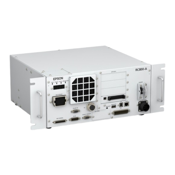
- Page 1 Robot Controller RC800-A Manual Original instructions Control Unit RC800-A ©Seiko Epson Corporation 2024-2025 Rev.3 ENM253C7164F...
-
Page 2: Table Of Contents
Robot Controller RC800-A Manual Rev.3 Table of Contents 1. Introduction 1.1 Introduction 1.2 Trademarks 1.3 Notation 1.4 Terms of Use 1.5 Manufacturer 1.6 Contact Information 1.7 Disposal 1.8 Disposal of Coin Cell Batteries 1.8.1 For Customers in the European Union 1.8.2 For Customers in the Taiwan Region... - Page 3 Robot Controller RC800-A Manual Rev.3 3.5.5 Peripheral Equipment Design 3.5.6 Remote Control 3.5.7 Power Off During Manipulator Operation 3.5.8 Emergency Stop 3.5.9 Safeguard (SG) 3.5.10 Presence Sensing Device 3.5.11 Resetting Safeguards 3.5.12 Robot Operation Panel 3.6 Connections 3.6.1 Connection of Interlocked Guard Switch (Safety Device) and Emergency Stop Switch 3.6.2 Controller Power Supply...
- Page 4 Robot Controller RC800-A Manual Rev.3 3.10.1.3 Force Sensor (Option) 3.10.1.4 Conveyor Tracking (Option) 3.10.1.5 RS-232C (Option) 3.10.1.6 Analog I/O Board (Option) 3.10.2 Connecting the Teach Pendant (Option) 4. Function Information 4.1 Specifications 4.1.1 System Configuration Example 4.1.2 Safety Functions 4.1.2.1 Types of Safety Functions 4.1.2.2 Safety Functions...
- Page 5 4.6.2.1 Notes 4.6.2.2 Supported USB Memory Devices 4.6.3 Using the Controller Backup Function 4.6.3.1 Controller Backup by Trigger Button 4.6.3.2 Data Loading by Epson RC+ 4.6.3.3 Forwarding by E-mail 4.6.4 Details of Saved Data 4.7 LAN (Ethernet Communication) Port 4.7.1 What is a LAN (Ethernet Communication) Port? 4.7.2 IP Addresses...
- Page 6 Robot Controller RC800-A Manual Rev.3 4.9.3.2 Example 2: When External Safety Relay is Connected 4.10 Safety I/O Connector 4.10.1 Safety I/O 4.10.2 Signal Arrangement 4.10.3 Safety Inputs 4.10.3.1 Safety Input Specifications 4.10.3.2 Connecting as Emergency Stop 4.10.3.3 Connecting as Safeguard 4.10.3.4 Connecting as Safety Function Switching Device...
- Page 7 4.14.2 Expansion I/O Boards 4.14.2.1 Expansion I/O Boards 4.14.2.2 Board Settings (Expansion I/O Board) 4.14.2.3 Checking with Epson RC+ (Expansion I/O Board) 4.14.2.4 Input Circuit (Expansion I/O Board) 4.14.2.5 Output Circuit (Expansion I/O Board) 4.14.2.6 Signal Arrangement (Expansion I/O Board) 4.14.3 RS-232C Board...
- Page 8 Robot Controller RC800-A Manual Rev.3 5.2.4 Restore 5.3 Alarm Function 5.3.1 Maintenance 5.3.2 Viewing the Maintenance Information 5.3.3 Editing the Maintenance Information 5.3.4 Alarm Notification Procedure 5.3.5 Resetting an Alarm 6. Appendix 6.1 Appendix A: Option Parts List 6.2 Appendix B: Bundled Accessories 6.3 Appendix C: Troubleshooting...
-
Page 9: Introduction
Robot Controller RC800-A Manual Rev.3 1. Introduction... -
Page 10: Introduction
Epson conducts rigorous testing and inspection to ensure that the performance of our robot systems meets our standards. Please note that if the Epson robot system is used outside the operating conditions described in the manual, the product will not perform up to its basic performance. -
Page 11: Disposal
Robot Controller RC800-A Manual Rev.3 The Safety Manual is also available at the following site. URL: https://download.epson.biz/robots/ 1.7 Disposal When disposing of this product, please do so in accordance with the laws and regulations of your country. 1.8 Disposal of Coin Cell Batteries Refer to the following manual for the removal and replacement procedures for coin cell batteries. -
Page 12: For Customers In The Taiwan Region
Security measures for network connections Epson robot systems are designed to be used within a closed local area network. Please refrain from connecting to networks with Internet access. If a connection to the Internet is required, please implement the necessary technical measures* to protect from malicious attacks and vulnerabilities over the Internet. -
Page 13: Setting By Using Software
Operator Panel OP1 Teach Pendant TP1 For RC800-A, be sure to install Epson RC+ to the development PC first, and then connect the development PC and RC800-A with the USB cable. If RC800-A and the development PC are connected without installing Epson RC+ to the development PC, the [Add New Hardware Wizard] appears. -
Page 14: Manual Types For This Product
Manuals are available for each option. Maintenance and servicing manuals Manuals for maintenance and servicing are not included with the product. Maintenance should be performed by people who have received maintenance training provided by Epson and the suppliers. For more information, please contact the supplier. -
Page 15: Safety
Robot Controller RC800-A Manual Rev.3 2. Safety... -
Page 16: Safety
After reading this manual, store it in an easily accessible location for future reference. This product is a dedicated device for Epson robots to be used in an industrial environment for the transport and assembly of components in a safe, isolated area. - Page 17 Robot Controller RC800-A Manual Rev.3 ISO 12100 Safety of machinery -- General principles for design -- Risk assessment and risk reduction ISO 13849-1 Safety of machinery -- Safety-related parts of control systems -- Part 1: General principles for design ISO 13850...
-
Page 18: Role For Safety Managers
Robot Controller RC800-A Manual Rev.3 2.3 Role for Safety Managers Safety managers should perform the following: Password management Training implementation 2.3.1 Password Management Safety managers should manage the following passwords: Epson RC+ security user password Safety board password Controller Ethernet connection password Teach Pendant TP4 T2 mode password 2.3.2 Training Implementation... - Page 19 Workers must have expertise and skill in installing power cables. Design, unpacking, and installation of robot systems Workers must have received the installation training provided by Epson and the supplier. Installation of optional circuit boards on Controllers/Installation of wall-mounted options Workers must have received the maintenance training provided by Epson and the supplier.
-
Page 20: Installation Of Robot System
Robot Controller RC800-A Manual Rev.3 3. Installation of Robot System This section describes the process from unpacking to operation of the robot system and the design of the robot system. It is primarily intended for those who carry in and install the robot system and for those who connect to the development PC... -
Page 21: System Configuration Example
"Manipulator Manual" 3.3 Manipulator Installation The robot and robotic equipment must be installed by staff who has received installation training conducted by Epson or its suppliers. Also, the laws and regulations of the installation country must be followed. Before using the robot system, be sure to check the basic safety information by referring to the following manual. -
Page 22: Designing A Safe Robot System
In addition to ensuring safe operation of the robot, it is also important that robot users give careful consideration to safety for the entire robot system that is designed. This section explains the minimum requirements that must be observed when using Epson robots in your robot systems. Please design and manufacture robot systems by following the principles described in this manual. -
Page 23: Peripheral Equipment Design
Robot Controller RC800-A Manual Rev.3 Design the robot hand such that its weight and moment of inertia do not exceed the allowable limits. Use of a robot hand that exceeds the allowable limits can subject the robot to excessive loads. This will not only shorten the service life of the robot but can lead to unexpectedly dangerous situations due to the additional external forces applied to the hand and the workpiece. -
Page 24: Safeguard (Sg)
Robot Controller RC800-A Manual Rev.3 Besides pressing the emergency stop switch when an emergency occurs, to stop the Manipulator during program operation, use the Pause or STOP (program stop) statements assigned to a standard I/O. The Pause and STOP statements do not turn off motor energization, and so the brake is not locked. -
Page 25: Presence Sensing Device
Robot Controller RC800-A Manual Rev.3 Installing safety barriers When installing safety barriers within the maximum range of the Manipulator, combine safety functions such as SLP. Carefully take into account the size of the hand and the workpieces to be held so that no interference occurs between the operating parts and the safety barriers. -
Page 26: Connections
Robot Controller RC800-A Manual Rev.3 3.6 Connections 3.6.1 Connection of Interlocked Guard Switch (Safety Device) and Emergency Stop Switch To ensure safety, connect a safeguard switch, emergency stop switch, or similar safety device to the safety I/O connector or emergency stop input connector of the Controller. Refer to the following sections for details. - Page 27 Robot Controller RC800-A Manual Rev.3 Wiring Only authorized or certified staff should be allowed to perform wiring. Wiring by unauthorized or uncertified staff may result in bodily injury and/or malfunction of the robot system. For cleanroom-models When the Manipulator is a cleanroom model, an exhaust system must be connected. For details on the exhaust system, refer to the following manual.
-
Page 28: Saving The Default Settings
Robot Controller RC800-A Manual Rev.3 3.7 Saving the Default Settings The Controller has already been configured with the purchased robot(s) at shipment. However, in case of data loss, we recommend saving the default Controller settings. A USB memory device is required to save the Controller settings. -
Page 29: Power On
Robot Controller RC800-A Manual Rev.3 3.8 Power On 3.8.1 Power On Notes Check of Manipulator Before operating the Manipulator, be sure that no parts of the Manipulator are missing and that it has no damage or other external defects. Missing parts or damage may cause malfunction of the Manipulator, is extremely hazardous, and may result in serious injury and/or severe equipment damage to the robot system. -
Page 30: Key Points
Emergency stop Press the emergency stop switch with the motor segment LED. operation energized. Emergency stop is displayed on the Epson RC+. SO is displayed on the Controller's 7- Safeguard operation Operate the safeguard with the motor energized. segment LED. -
Page 31: First Step
Rev.3 3.9 First Step This section presents the procedure for installing Epson RC+ to the development PC, connecting the development PC and the Controller by USB, and executing a simple program. First, make sure that the robot system is installed safely by following the information provided in "Safety" and "Installation."... -
Page 32: Connecting The Pc And The Controller Using The Development Pc Connection Usb Port
Status:] field. Check that "Connected" is displayed, and click the [Close] button to close the [PC to Controller Communications] dialog box. This completes the connection of the development PC and the Controller. The robot system can now be used from Epson RC+. 3.9.2.4 Backing Up the Controller Initial Status Back up the Controller setting data that was configured at shipment. -
Page 33: Disconnecting The Development Pc And The Controller
3.9.2.5 Disconnecting the Development PC and the Controller This explains the procedure for disconnecting the development PC and the Controller. 1. From the Epson RC+ menu, select [Setup] - [PC to Controller Communications] to display the [PC to Controller Communications] dialog box. -
Page 34: Initial Settings For Safety Function Parameters
Jog operation from Epson RC+ This section explains the following operation methods. A: Manual operation B: Command execution from Epson RC+ C: Jog operation from Epson RC+ A: Manual operation Move the robot by hand while it is in a non-energized state. - Page 35 1. Start Epson RC+. Double click the <Epson RC+> icon on the Desktop. You can also select from the Windows menu. 2. Open the command window.
- Page 36 Energize the robot motors, operate the robot from the Jog & Teach window of Epson RC+. 1. Start Epson RC+. Double click the <Epson RC+> icon on the Desktop. You can also select from the Windows menu. 2. Create a new project.
- Page 37 Robot Controller RC800-A Manual Rev.3 3. Turn on the motors. Check that the [Control Panel] tab is open. Click the [Motor: Off] button. 4. Perform jog operation. i. Select the [Jog & Teach] tab. ii. From [Jogging], select "Joint." iii. Click jog keys J1-J6 to operate the selected joint.
-
Page 38: Writing Your First Program
3.9.7 Writing Your First Program After installing the Controller and robot, and installing the Epson RC+ software on the PC, follow the procedure below to create a simple application program so that you will become more familiar with the Epson RC+ development environment. - Page 39 4. Run the program. i. Press F5 to display the Run window. (F5 is the shortcut key for selecting [Run] - [Run Window] in the Epson RC+ menu.) At the bottom of the main window, the Status window appears indicating the build operation status.
- Page 40 Robot Controller RC800-A Manual Rev.3 ✏ KEY POINTS Teaching of this procedure should be done outside the safeguard. 5. Teach robot points. i. Confirm whether safe robot operation is possible. Click the [Robot Manager] button on the toolbar. ii. Turn on the motors.
- Page 41 8. Back up the project and system settings. Back up the project and the Controller settings of the created program. Backups can be made easily using Epson RC+. It is...
- Page 42 USB memory device. Backup procedure for project and system settings: i. From the Epson RC+ menu, select [Project] - [Copy]. ii. In the [Copy Project] dialog box, change the [Destination Drive] box to the desired drive.
-
Page 43: Second Step
3.10.1 Connecting with External Equipment 3.10.1.1 Remote Control Refer to the following section. I/O Remote Settings "Epson RC+ User's Guide - Remote Control" Refer to the following section. I/O Connector Expansion I/O Boards "Epson RC+ User's Guide - I/O Setup"... -
Page 44: Rs-232C (Option)
Robot Controller RC800-A Manual Rev.3 3.10.1.5 RS-232C (Option) Refer to the following section. RS-232C Board "Epson RC+ User's Guide - RS-232C Communications" 3.10.1.6 Analog I/O Board (Option) Refer to the following section. Analog I/O Board 3.10.2 Connecting the Teach Pendant (Option) Refer to the following section. -
Page 45: Function Information
Robot Controller RC800-A Manual Rev.3 4. Function Information This section describes each function of the Robot Controller. This is primarily intended for those who want to learn more about Robot Controllers. -
Page 46: Specifications
"Epson RC+ User's Guide" *2 One of the Teach Pendants is controlled. *3 When connecting to RC800-A, a dedicated conversion cable is required. *4 The conveyor tracking I/F is equipped as standard, but a license is required to use it. -
Page 47: Safety Functions
Robot Controller RC800-A Manual Rev.3 4.1.2 Safety Functions 4.1.2.1 Types of Safety Functions This Controller has third-party certification. The certified safety functions are combined and defined as the following safety functions of Epson. The safety functions in this manual are described under Controller Safety Function Name. - Page 48 Port of the safety I/O connector configured for the safeguard (SG) Enable Enable is the path connected to the enable switch when the Teach Pendant is connected. Only Epson Teach Pendants can be connected, and customer enable switches cannot be connected.
-
Page 49: Safety Parameters
TEACH Enable TEST AUTO Soft Axis Limiting TEST E-Stop, TP Emergency Safety Stop Input Safety Outputs Enable AUTO TEST The B10D values for switches provided by Epson are as follows: Emergency Stop switch (Option and TP): 250,000 Enable switch: 1,000,000... -
Page 50: Specifications Table
Robot Controller RC800-A Manual Rev.3 4.1.3 Specifications Table Item Specifications Machine name Robot Controller Product series RC800-A There are two models, A and B, which differ based on appearance. For details, refer to the following section. Part Names and Their Functions... - Page 51 Robot Controller RC800-A Manual Rev.3 Item Specifications 1 port Ethernet 10BASE-T, 100BASE-TX, 1000BASE-T Development PC 1 port, TypeB Connection USB Port Communication interface 1 port, TypeA (standard) Use a USB memory device that meets the following conditions: - USB 2.0/3.0 compatible...
- Page 52 Robot Controller RC800-A Manual Rev.3 Item Specifications Short-circuit 5 kA current rating Maximum TN: 0.32Ω allowable fault TT: 200Ω loop impedance Insulation 100 MΩ min. resistance Installation 5 to 40°C Ambient temperature Transportation, storage - 20 to 60°C Ambient Installation...
-
Page 53: Dimensions
Robot Controller RC800-A Manual Rev.3 4.1.4 Dimensions Model A Standard (Units: mm) After Mounting Rack Mounting Option... - Page 54 Robot Controller RC800-A Manual Rev.3 After Mounting Wall Mounting Option Model B Standard (Units: mm)
- Page 55 Robot Controller RC800-A Manual Rev.3 After Mounting Rack Mounting Option After Mounting Wall Mounting Option...
-
Page 56: Part Names And Their Functions
Robot Controller RC800-A Manual Rev.3 4.2 Part Names and Their Functions RC800-A Model A Model B [ a ] Face plate label This label contains the Controller's serial number and other information. [ b ] 7-segment display This is a 4-digit, 7-segment LED that is used to indicate the line number, and the Controller status (error number, warning number, emergency stop, or safeguard status). - Page 57 Robot Controller RC800-A Manual Rev.3 [ c ] Serial number label for connected Manipulator This label indicates the Manipulator to be connected. It contains the Manipulator model and serial number. MANIPULATOR GXxxxxx 00001 [ d ] M/C POWER connector This is the power supply connector for the Manipulator.
- Page 58 Refer to the following section. TP Port ✏ KEY POINTS Do not connect the following devices to the TP port of RC800-A. The different signal arrangement could cause a breakdown in the device. Dummy plug (optional device) Operation Pendant OP500...
-
Page 59: Lockout Mechanism
Robot Controller RC800-A Manual Rev.3 Refer to the following section. Power Supply - AC Power Cable [ q ] POWER switch This is the power switch for the Controller. [ r ] Option slots These slots are for mounting dedicated optional boards (expansion I/O board, RS-232C board, pulse generator board, and analog I/O board). - Page 60 Robot Controller RC800-A Manual Rev.3 2. Keep the padlock locked.
-
Page 61: Connecting The Cables
Robot Controller RC800-A Manual Rev.3 4.3 Connecting the Cables 4.3.1 Connection Example... -
Page 62: Connecting Controllers And Manipulators
Robot Controller RC800-A Manual Rev.3 4.3.2 Connecting Controllers and Manipulators A power cable and signal cable are used to connect the Controller to the Manipulator. WARNING Before connecting or disconnecting cables, be sure to shut off the AC power input sections. This includes turning off the Controller and related equipment, unplugging the power cable from the outlet, and so on. - Page 63 Robot Controller RC800-A Manual Rev.3 7-segment LED All 4-digit 7 segments are turned off. After Controller startup The LEDs (TEST, TEACH, AUTO, PROGRAM) corresponding to the current operation mode (TEST, TEACH, AUTO, PROGRAM) turn on. 7-segment LED The displayed information changes depending on the Controller status.
-
Page 64: Displays Of Special States
If this occurs after maintenance, confirm that each harness is software terminated properly connected to the board. Display: 9997 Epson RC+ (software) or the Teach This is the normal display when the system is shut down. No action Pendant (optional) issued a command to is required. -
Page 65: Protective Functions
Robot Controller RC800-A Manual Rev.3 segment State Remedy Display System storage initialization The numeric value represents the The data is updating. Do not turn off the power until the indicator initialization status. disappears. 00 % to 99 % Restart the Controller. -
Page 66: Overvoltage Detection
Robot Controller RC800-A Manual Rev.3 Relay melting detection This detects melting or open failure of relay contacts. Overvoltage detection This detects overvoltage errors in the Controller. AC power voltage drop detection This detects a drop in the power supply voltage. -
Page 67: Installation
Robot Controller RC800-A Manual Rev.3 4.4 Installation 4.4.1 Bundled Accessories For details about bundled accessories, refer to the following section. Appendix B: Bundled Accessories 4.4.2 Installation Requirements WARNING Do not disassemble the product in areas not described in the manual or perform maintenance in a manner different from these procedures. -
Page 68: Installation Surface
Robot Controller RC800-A Manual Rev.3 Electrostatic noise 4 kV or less Base table The Controller should be installed 0.4 to 2 meters above the floor for ease of maintenance. The power shut-off switch should be installed at a height of 0.6 to 1.9 meters from the floor. - Page 69 Robot Controller RC800-A Manual Rev.3 (B) Vertical mounting * The rubber feet on the bottom need to be replaced. Attach the rubber feet with the flat side facing the Controller. Remove the screws that contact the rubber feet. The size of the screws securing the rubber feet is M4 × 8.
- Page 70 Robot Controller RC800-A Manual Rev.3 (A) Flat mounting, (C) Rack mounting (Illustration shows flat mounting.) Symbol Description 50 mm Controller fan air direction (excluding Controllers that do not have a fan) 200 mm (excluding mounting surfaces such as the base table)
-
Page 71: Wall Mounting Option
Robot Controller RC800-A Manual Rev.3 Symbol Description Controller fan air direction (excluding Controllers that do not have a fan) 200 mm (excluding mounting surfaces such as the base table) 100 mm 50 mm 50 mm * Leave a space of at least 200 mm to ensure easy access for maintenance. -
Page 72: Power Supply
Robot Controller RC800-A Manual Rev.3 4.4.3 Power Supply 4.4.3.1 Power Supply Specifications Prepare an AC power supply that meets the following specifications. Item Specifications Rated voltage 200 to 240 VAC (±10%) Number of phases Single phase Frequency 50 / 60 Hz... - Page 73 Robot Controller RC800-A Manual Rev.3 Item Specifications Capacity 3.5 kVA % Impedance 2.1% or more If installed in North America, the transformer overload protection should be in accordance with NFPA 70. The requirements of EN 60364-4-41 must be satisfied under the following conditions.
-
Page 74: Ac Power Cable
Robot Controller RC800-A Manual Rev.3 4.4.3.2 AC Power Cable WARNING All work operations should be performed by people with specialized knowledge and skills in the field. The ground wire (green/yellow) of the AC power cable must be connected to the ground terminal of the power distribution system. - Page 75 Robot Controller RC800-A Manual Rev.3 Model A When connecting the plug of the AC power cable to the Controller, insert until it clicks into place as shown in the figure below.
- Page 76 Robot Controller RC800-A Manual Rev.3 Model B 1. Screw the AC power cable to the terminal block (in three places). When connecting the wires to the Controller, match the characters of the Controller display and the wires' identification labels. The order is L, N, and PE from the left.
-
Page 77: Key Points For Noise Reduction
Robot Controller RC800-A Manual Rev.3 4.4.4 Key Points for Noise Reduction Pay attention to the following points when wiring to minimize the effect of noise. The power supply must be grounded to a class D ground (grounding resistance of 100 Ω or less). -
Page 78: Symbol Description
Robot Controller RC800-A Manual Rev.3 Ground the cable shield section. Symbol Description Remove outer sheath and affix with an FG clamp Screw into the Controller and ground it Attach ferrite core to cable. Symbol Description Ferrite core The following EMC measures should be implemented for the AC power cable, MC cable, and each communication cable if necessary. -
Page 79: Operation Modes (Teach, Auto, Test)
Robot Controller RC800-A Manual Rev.3 4.5 Operation Modes (TEACH, AUTO, TEST) 4.5.1 Overview of Operation Modes The robot system has three modes. WARNING When teaching, a supervisor should be positioned outside the safety barriers so that the robot can be stopped immediately if an anomaly occurs. -
Page 80: Switching Operation Modes
Robot Controller RC800-A Manual Rev.3 4.5.2 Switching Operation Modes WARNING Operation is switched between TEACH mode and AUTO mode by the mode selector keyswitch on the Teach Pendant. When switching modes, be sure to switch when outside the safety barriers to avoid hazards. -
Page 81: Program Mode (Auto)
4.5.3.2 Settings from Epson RC+ This section describes the procedure for entering program mode from Epson RC+. 1. In the Epson RC+ menu, select [Setup] - [System Configuration] to display the [System Configuration] dialog box. 2. Select [Startup] - [Start Mode]. -
Page 82: Settings From Epson Rc
4.5.4.2 Settings from Epson RC+ This section describes the procedure for entering automatic operation mode from Epson RC+. 1. In the Epson RC+ menu, select [Setup] - [System Configuration] to display the [System Configuration] dialog box. 2. Select [Startup] - [Start Mode]. - Page 83 Robot Controller RC800-A Manual Rev.3 1. In the Epson RC+ menu, select [Setup] - [System Configuration] to display the [System Configuration] dialog box. 2. Select [Controller] - [Configuration]. 3. From [Controller Configuration] - [Control Device], select one of the following two types.
-
Page 84: Memory Port
This function allows various information (data) of the Controller to be saved to a USB memory device at the push of a button. Data saved on a USB memory device can be loaded by Epson RC+ to accurately and easily determine the status of the Controller and program. -
Page 85: Data Loading By Epson Rc
4.6.3.2 Data Loading by Epson RC+ For details on the procedure for using Epson RC+ to load data saved on a USB memory device and to display the Controller status, refer to the following manual. -
Page 86: Details Of Saved Data
Safety Board related items: SFConfig.txt Information of the Safety Board is saved here. Project related files: In the Epson RC+ menu, select [Setup] - [System Configuration] to display the [System All files related to the project Configuration] dialog box. except project name.obj The project is saved when the [Include project files when status exported] box is selected in the menu - [Controller] - [Preferences] dialog box. - Page 87 Robot Controller RC800-A Manual Rev.3 *1 You can choose not to save "All files related to the project except project name.obj" by deselecting the setting option. *2 You can select to include the data for error analysis in "X_Y.dat" in the data to be saved according to the Preferences or the...
-
Page 88: Lan (Ethernet Communication) Port
"Epson RC+ User's Guide - Setting Password for PC Ethernet Controller Connection" Epson robot systems are designed to be used within a closed local area network. To ensure security, the setting of a global IP address is now considered as access to the Internet, and so a password is required to authenticate the connection. -
Page 89: Controller Ip Address Change Procedure
Refer to the following section. Connecting the Development PC and the Controller 2. In the Epson RC+ menu, select [Setup] - [System Configuration] to display the [System Configuration] dialog box. 3. Select [Controller] - [Configuration]. 4. Set appropriate values for the IP address and subnet mask, and click the [Apply] button. - Page 90 Robot Controller RC800-A Manual Rev.3 3. Start the Epson RC+ software. 4. From the Epson RC+ menu, select [Setup] - [PC to Controller Communications] to display the [PC to Controller Communications] dialog box. 5. Click the [Add] button. 6. Perform the following settings and then click the [OK] button.
-
Page 91: Disconnecting The Development Pc And Controller Via Ethernet
Status:] field. Check that "Connected" is displayed, and click the [Close] button to close the [PC to Controller Communications] dialog box. This completes the connection of the development PC and the Controller. The robot system can now be used from Epson RC+ over an Ethernet connection. -
Page 92: Tp Port
An external enable switch cannot be connected to the TP port. Use the enable switch provided with the Teach Pendant. 4.8.2 Connecting a Teach Pendant The Teach Pendants come with a dedicated cable for the RC700-A, RC700-D, RC700-E ,and RC800-A Controllers. Connect the connector of this cable to the TP port. -
Page 93: Emergency Stop Input Connector
Details about the safety requirements in this section are provided in the following manual. Read together with this manual to ensure safety. "Epson RC+ User's Guide - Safety" CAUTION Before use, confirm that the emergency stop and safeguard functions work properly not only when starting up but also when any changes are made from the previous usage state, such as after the safety function settings are changed, options are added, or parts are replaced for maintenance. -
Page 94: Connecting An Emergency Stop Switch
Robot Controller RC800-A Manual Rev.3 ✏ KEY POINTS If nothing is connected to the emergency stop input connector, the Controller enters an emergency stop state. When this connector is not used, connect the EMERGENCY connector short plug. When unplugging the cable, pull it out while pressing down the lever on the cable-side connector. -
Page 95: Emergency Stop Switch Function Check
1. With the emergency stop switch pressed down, turn on the power to start the Controller. 2. Check that the 7-segment LED on the Controller displays the following. 3. Check that [EStop] is displayed on the Epson RC+ status bar. 4. Release the emergency stop switch. -
Page 96: Signal Arrangement And Electrical Specifications
Robot Controller RC800-A Manual Rev.3 4.9.2 Signal Arrangement and Electrical Specifications The signal arrangement of the emergency stop input connector is shown in the following table. Pin Number Signal Name Function 24 V for emergency stop Internal 24 V output... -
Page 97: Wiring Examples
Robot Controller RC800-A Manual Rev.3 4.9.3 Wiring Examples 4.9.3.1 Example 1: When External Emergency Stop Switch is Connected... -
Page 98: Example 2: When External Safety Relay Is Connected
Robot Controller RC800-A Manual Rev.3 4.9.3.2 Example 2: When External Safety Relay is Connected... -
Page 99: Safety I/O Connector
Robot Controller RC800-A Manual Rev.3 4.10 Safety I/O Connector 4.10.1 Safety I/O This Controller has safety-compliant safety inputs (5ch) and safety outputs (3ch). Safety inputs (category 3 PLd) Safety outputs (category 3 PLd) Emergency stop switches, safeguards, laser curtains, and similar devices can be connected to the safety inputs. -
Page 100: Signal Arrangement
Robot Controller RC800-A Manual Rev.3 4.10.2 Signal Arrangement Check the orientation of the connectors before connecting them. Signal Arrangement of Safety I/O Connector (XW4N-28D2 Male) Signal Name Function Signal Name Function Number Number External GND SAFETY_IN_COM- Safety input common Ex-GND... -
Page 101: Safety Inputs
Robot Controller RC800-A Manual Rev.3 4.10.3 Safety Inputs The safety inputs have a redundant circuit design, and an error occurs if the inputs are mismatched for two or more seconds. The safety inputs have five channels, with independent input terminals and one 24 V/GND terminal (COM) common to all five channels. -
Page 102: Connecting As Emergency Stop
Robot Controller RC800-A Manual Rev.3 4.10.3.2 Connecting as Emergency Stop In addition to the emergency stop input connector, an emergency stop switch can also be used with the safety I/O connector. An external power supply is required when using an emergency stop switch with the safety I/O connector. - Page 103 Robot Controller RC800-A Manual Rev.3 Safety relay: Connection pattern 1 Safety relay: Connection pattern 2...
-
Page 104: Connecting As Safeguard
Robot Controller RC800-A Manual Rev.3 4.10.3.3 Connecting as Safeguard To maintain a safe working zone, safety barriers must be set up around the Manipulator. The safety barriers must have an safety devices at the entrance and exit to the working zone. The term "safeguard" as used in this manual refers to a safety device with an interlock that allows entry into the safety barriers. - Page 105 Robot Controller RC800-A Manual Rev.3 Checking the switch function After connecting the safeguard switch and latch release switch to the safety I/O connector, a safety check must be performed. Use the following procedure to check the function of the switch before operating the Manipulator.
-
Page 106: Connecting As Safety Function Switching Device
Robot Controller RC800-A Manual Rev.3 When a safeguard and laser curtain are connected 4.10.3.4 Connecting as Safety Function Switching Device The SLS and SLP settings need to be switched to match the customer's usage environment. The safety input can be used as the switching function. -
Page 107: Safety Outputs
Robot Controller RC800-A Manual Rev.3 4.10.4 Safety Outputs The safety outputs have a redundant circuit design, and an error occurs if the inputs are mismatched for two or more seconds. There are three channels for safety outputs, each with independent output terminals. To use the output terminals, external 24 V and GND power must be supplied. - Page 108 Robot Controller RC800-A Manual Rev.3 When Safety Relay is connected Insert a diode for circuit protection.
-
Page 109: I/O Connector
Robot Controller RC800-A Manual Rev.3 4.11 I/O Connector I/Os are connectors for user input/output devices. POINTS Pin Number Inputs 0-23 Outputs 0-15 For details on expansion I/Os installed in the option unit, refer to the following section. Expansion I/O Boards When wiring, refer to the following section to prevent noise generation. -
Page 110: Input Circuit Diagram And Wiring Example
Robot Controller RC800-A Manual Rev.3 4.11.1.1 Input Circuit Diagram and Wiring Example 1... - Page 111 Robot Controller RC800-A Manual Rev.3 4.11.1.2 Input Circuit Diagram and Wiring Example 2...
-
Page 112: Output Circuit
Robot Controller RC800-A Manual Rev.3 4.11.2 Output Circuit Rated output voltage: +12 V to 24 V ±10%. Maximum output current: 100 mA per output Output driver: PhotoMOS relay On-resistance (average): 23.5 Ω or less The output circuit uses a non-polarized PhotoMOS relay, which allows the following two types of wiring. -
Page 113: Output Circuit Diagram And Wiring Example 1: Sink Type (Npn)
Robot Controller RC800-A Manual Rev.3 4.11.2.1 Output circuit diagram and wiring example 1: Sink type (NPN) -
Page 114: Output Circuit Diagram And Wiring Example 2: Source Type (Pnp)
Robot Controller RC800-A Manual Rev.3 4.11.2.2 Output circuit diagram and wiring example 2: Source type (PNP) 4.11.3 Signal Arrangement Signal Name Signal Name Number Number Input common No. 0 to 7 Input No. 15 Input No. 0 (Start) Output No. 6 (SError) Input No. - Page 115 Robot Controller RC800-A Manual Rev.3 Signal Name Signal Name Number Number Input No. 4 (Stop) Output No. 10 Input No. 5 (Pause) Not used Output common No. 8 to Input No. 6 (Continue) Input No. 7 (Reset) Input common No. 16 to 23 Output No.
- Page 116 Robot Controller RC800-A Manual Rev.3 By default, the remote functions shown in parentheses ( ) are assigned to the I/O of inputs 0 to 7 and outputs 0 to 8. To assign remote functions, refer to the following section. I/O Remote Settings...
-
Page 117: I/O Remote Settings
By default, remote functions are assigned to the I/O of input numbers 0 to 7 and output numbers 0 to 8. To change the function assignments from the default settings, the settings must be made using Epson RC+. An expansion I/O board or Fieldbus I/O board is required to output all functions. - Page 118 Robot Controller RC800-A Manual Rev.3 ✏ KEY POINTS If an error occurs, execute "Reset" to clear the error state before executing a remote input command. Use "Error output" and "Reset input" to allow the remote device to monitor and clear error states.
- Page 119 Robot Controller RC800-A Manual Rev.3 Input Function Name Default Description Acceptance Condition (*1) Operate under a forced low power function Always Robot operates at low power This input is Does not accept Power High control by commands, etc. accepted even...
- Page 120 Robot Controller RC800-A Manual Rev.3 Input Function Name Default Description Acceptance Condition (*1) Ready output ON Error output OFF EStopOn output SafeguardOn output OFF Home Not set Move robot arm to user-defined home position EStopOff output MotorsOn output Pause input OFF...
- Page 121 Robot Controller RC800-A Manual Rev.3 Input Function Name Default Description Acceptance Condition (*1) Input the input signal for performing alive monitoring of the Controller The same signal as the input is output to the output-side ALIVE Not set ALIVE. The master device can perform alive monitoring of the Controller by periodically switching inputs and checking output signals.
- Page 122 (*5) This resumes the execution of a paused task. The setting for "Auto safeguard position recovery" setting in the Controller preferences is for control from Epson RC+ 8.0. This is not a setting to enable or disable the recovery operation of this command.
- Page 123 (*14) After the safeguard is closed, perform the recovery operation to the position when the safeguard is open. The setting for "Auto safeguard position recovery" setting in the Controller preferences is for control from Epson RC+ 8.0. This is not a setting to enable or disable the recovery operation of this command.
- Page 124 Robot Controller RC800-A Manual Rev.3 Function Initial Input Acceptance Description Name Value Condition SelAxis1 SelAxis2 Not set Specify axis number for executing command (*b) AutoMode output ON SelAxis4 (*a) This switches the conditions for reflecting Maintenance. The conditions are selected using SelAxis1-SelAxis4, and this signal can be set to switch the reflection conditions.
-
Page 125: Outputs
Robot Controller RC800-A Manual Rev.3 SelCtrlParts SelCtrlParts SelCtrlParts SelCtrlParts Parts (Controller) (Reserved) (Reserved) 0=OFF, 1=ON (*17) The conditions are selected using SelRbParts1-SelRbParts8, and ResetRbParts clears the robot's Maintenance information. Function Name Initial Value Description Input Acceptance Condition ResetRbParts Not set... - Page 126 Robot Controller RC800-A Manual Rev.3 Remote output always outputs the status of the assigned function externally, regardless of the control device settings. Output is performed automatically, and so there is no need to create a special program. Function Name Default...
- Page 127 Robot Controller RC800-A Manual Rev.3 Function Name Default Description TeachMode Not set ON when in TEACH mode (*3) TestMode Not set ON when in TEST mode EnableOn Not set ON when enable switch is on (*3) ErrorCode1 to Not set...
- Page 128 Robot Controller RC800-A Manual Rev.3 Function Name Default Description ExtResp_32-47 Not set ExtResp_48-63 Not set ExtResp_64-79 Not set "Remote Control Reference - Remote I/O to Be Used" ExtResp_80-95 Not set ExtResp_96-111 Not set ExtResp_112- Not set GetPartsStsCtrl0- Not set Maintenance status (Controller) (*12)
- Page 129 When in program mode and remote I/O is enabled (*7) For details, refer to the following manual or online help. "Epson RC+ Language Reference - Box" (*8) For details, refer to the following manual or online help. "Epson RC+ Language Reference - Plane"...
- Page 130 Robot Controller RC800-A Manual Rev.3 Parts (Robot) Battery Timing belt Grease Motor Reduction gear Ball screw spline (Reserved) (Reserved) (Reserved)
-
Page 131: Timing Charts
Robot Controller RC800-A Manual Rev.3 4.12.2 Timing Charts 4.12.2.1 Input Signal Notes The timing charts show the timing for the Controller's key operations. Be sure to follow the timing chart when inputting signals. However, note that the times in the charts are approximate. The time varies depending on the number of Manipulators, the number of tasks running, the Controller's CPU speed, and other factors. -
Page 132: Timing For Program Execution Sequence
Robot Controller RC800-A Manual Rev.3 4.12.2.3 Timing for Program Execution Sequence (Units: msec) * This varies depending on the Quick Pause (QP) setting and the program operation state at PAUSE input. 4.12.2.4 Timing forf Emergency Stop Sequence (Units: msec) (*1) This is the logical signal that indicates the timing of Controller internal processing. -
Page 133: R-I/O Connector
By combining this functionality with Vision, applications can be created that perform everything from workpiece pickup to alignment and installation without stopping the robot. For details, refer to the following manual. "Epson RC+ User's Guide - Real-time I/O" 4.13.1 Input Circuit Input voltage range: +24 V ±10% Input current: 5 mA Typ. - Page 134 Robot Controller RC800-A Manual Rev.3 Input circuit diagram and wiring example 2...
-
Page 135: Signal Arrangement
Robot Controller RC800-A Manual Rev.3 4.13.2 Signal Arrangement CAUTION When using R-I/O, pay attention to the following points. Using I/O with remote settings without satisfying the requirements may lead to system failure or safety issues. Use shielded cables, and route them as far away as possible from noise sources in the surrounding area. -
Page 136: Option Slots
Robot Controller RC800-A Manual Rev.3 4.14 Option Slots 4.14.1 What is an Option Slot? An option slot is a slot for installing an option board. Up to three option boards can be installed on the Controller. Expansion I/O Boards RS-232C Board... -
Page 137: Checking With Epson Rc+ (Expansion I/O Board)
Therefore, no software configuration is required. You can confirm on the Epson RC+ screen that the board was correctly recognized. 1. In the Epson RC+ menu, select [Setup] - [System Configuration] to display the [System Configuration] dialog box. 2. Select [Controller] - [Inputs / Outputs]. -
Page 138: Input Circuit (Expansion I/O Board)
Robot Controller RC800-A Manual Rev.3 3. Make sure that the installation is set to "Yes." The expansion I/O board is recognized by the Controller software. The corresponding inputs and outputs can be used. 4.14.2.4 Input Circuit (Expansion I/O Board) Input voltage range: +12 to 24 V ±10% ON voltage: +10.8 V (Min.) - Page 139 Robot Controller RC800-A Manual Rev.3 Input circuit diagram and wiring example 2: Sink type...
-
Page 140: Output Circuit (Expansion I/O Board)
Robot Controller RC800-A Manual Rev.3 4.14.2.5 Output Circuit (Expansion I/O Board) Rated output voltage: +12 V to 24 V ±10% Maximum output current: Typ. 100 mA per output Output driver: Photocoupler CAUTION There are two types of output circuits: sink type and source type. These types are set at factory shipping. - Page 141 Robot Controller RC800-A Manual Rev.3 Output Circuit Diagram and Wiring Example 1: Sink Type (NPN)
- Page 142 Robot Controller RC800-A Manual Rev.3 Output Circuit Diagram and Wiring Example 2: Source Type (PNP)
-
Page 143: Signal Arrangement (Expansion I/O Board)
Robot Controller RC800-A Manual Rev.3 4.14.2.6 Signal Arrangement (Expansion I/O Board) This is the signal arrangement table for the first expansion I/O board. Connector 1 signal arrangement Pin Number Signal Name Pin Number Signal Name Input common No. 64 to 71 Input No. - Page 144 Robot Controller RC800-A Manual Rev.3 Pin Number Signal Name Pin Number Signal Name Input No. 74 Output No. 78 Input No. 75 Output No. 79 Input No. 76 Not used Input No. 77 Not used Input No. 78 Not used...
- Page 145 Robot Controller RC800-A Manual Rev.3 This is the signal arrangement table for the second expansion I/O board. Connector 1 signal arrangement Pin Number Signal Name Pin Number Signal Name Input common No. 96 to 103 Input No. 111 Input No. 96 Output No.
- Page 146 Robot Controller RC800-A Manual Rev.3 Pin Number Signal Name Pin Number Signal Name Input No. 106 Output No. 110 Input No. 107 Output No. 111 Input No. 108 Not used Input No. 109 Not used Input No. 110 Not used...
- Page 147 Robot Controller RC800-A Manual Rev.3 This is the signal arrangement table for the third expansion I/O board. Connector 1 signal arrangement Pin Number Signal Name Pin Number Signal Name Input common No. 128 to 135 Input No. 143 Input No. 128 Output No.
-
Page 148: Port Numbers
Robot Controller RC800-A Manual Rev.3 Pin Number Signal Name Pin Number Signal Name Input No. 138 Output No. 142 Input No. 139 Output No. 143 Input No. 140 Not used Input No. 141 Not used Input No. 142 Not used... -
Page 149: Checking From Epson Rc+ (Rs-232C)
232C board. Therefore, no software configuration is required. You can confirm on the Epson RC+ screen that the board was correctly recognized. 1. In the Epson RC+ menu, select [Setup] - [System Configuration] to display the [System Configuration] dialog box. -
Page 150: Communication Settings (Rs-232C)
For details on how to use the RS-232C communication function from the robot application, refer to the following manual or online help. "Epson RC+ User's Guide - RS-232C Communications" 4.14.3.5 Communication Cable (RS-232C) Communication cables must be provided by the customer. -
Page 151: Pulse Generator Board
A pulse generator board can be used in two ways. For details, refer to the following manuals. When using as a conveyor encoder For details, refer to the following manual. "Epson RC+ User's Guide - Conveyor Tracking" When using as a PG motion system For details, refer to the following manual. - Page 152 Robot Controller RC800-A Manual Rev.3 Schematic overview of analog I/O board Rv: Voltage input terminating resistor (100 kΩ), Rc: Current input terminating resistor...
-
Page 153: Board Settings (Analog I/O Board)
Robot Controller RC800-A Manual Rev.3 4.14.5.2 Board Settings (Analog I/O Board) Switch and jumper settings 1. Address setting (SW1): Optional board addresses Settings 1st Board 2nd Board 3rd Board S5 to S8: Not used. Leave these at OFF. 2. Analog output: Settings... - Page 154 Robot Controller RC800-A Manual Rev.3 SWD1 (Current-Voltage Selector) Channel Output Mode Range Setting ±5 V ±10 V Voltage output mode 0 to 5 V DAC 1ch Not used Not used Not used 0 to 10 V 0 to 20 mA...
- Page 155 Robot Controller RC800-A Manual Rev.3 * Default: DAC default settings (voltage output: 0 to 10 V) 3. Analog input: Settings Current-voltage selector jumper (CN8/CN9): Current input/voltage input Short pins 1-2: Voltage input setting Short pins 2-3: Current input setting Current-voltage selector switch (SWD1): Current input/voltage input...
-
Page 156: Channel Input Mode
Robot Controller RC800-A Manual Rev.3 Range CN8 (Current-Voltage CN9 (Current-Voltage Channel Input Mode Setting Selector) Selector) ±5.12 V Short 1-2 ±10.24 V Short 1-2 Voltage input mode 0 to 5.12 V Short 1-2 Not used Short 1-2 0 to 10.24 V... -
Page 157: Channel Settings
You can confirm on the Epson RC+ screen that the board was correctly recognized. 1. In the Epson RC+ menu, select [Setup] - [System Configuration] to display the [System Configuration] dialog box. 2. Select [Controller] - [Inputs / Outputs] - [Analog I/O]. -
Page 158: Input Circuit (Analog I/O Board)
Robot Controller RC800-A Manual Rev.3 4.14.5.4 Input Circuit (Analog I/O Board) Input resolution: 16 bits Input range (voltage): 0 to 5.12 V, 0 to 10.24 V, ±5.12 V, ±10.24 V Input range (current): 0 to 24 mA Input impedance (voltage/current): approx. 100 kΩ/approx. 422 Ω... -
Page 159: Signal Arrangement (Analog I/O Board)
Robot Controller RC800-A Manual Rev.3 4.14.5.6 Signal Arrangement (Analog I/O Board) 1CH specification Pin Number Signal Name Pin Number Signal Name VOUT (DAC 1ch) Shield (DAC 1ch) COM (DAC 1ch) IOUT (DAC 1ch) Shield (DAC 1ch) COM (DAC 1ch) Not used... - Page 160 Robot Controller RC800-A Manual Rev.3 4CH specification Pin Number Signal Name Pin Number Signal Name VOUT (DAC 1ch) Shield (DAC 1ch) COM (DAC 1ch) IOUT (DAC 1ch) Shield (DAC 1ch) COM (DAC 1ch) Not used Not used Not used Not used...
-
Page 161: Fieldbus I/O
For details, refer to the following manuals. Robot Controller Option Fieldbus I/O "Epson RC+ User's Guide - Fieldbus Slave I/O" For details on installing the Fieldbus I/O module, refer to the following manual. "RC800-A Service Manual - Fieldbus I/O Module"... -
Page 162: Force Sensor I/F
"Force Guide - Hardware - Connection Example" 4.16.2 Checking from Epson RC+ (Force Sensor Port) 1. In the EPSON RC+ menu, select [Setup] - [System Configuration] to display the [System Configuration] dialog box. 2. Select [Controller] - [Force Sensor]. For details on setting the Force Sensor unit, refer to the following manual. -
Page 163: Conveyor Tracking Option I/F
4.17.2 Checking from Epson RC+ (Conveyor Tracking) 1. In the EPSON RC+ menu, select [Setup] - [System Configuration] to display the [System Configuration] dialog box. 2. Select [Conveyor Encoder]. For details on the setting conveyor tracking option, refer to the following manual. -
Page 164: Periodic Inspection
Robot Controller RC800-A Manual Rev.3 5. Periodic Inspection Accurate inspection work is necessary to prevent breakdowns and ensure safety. This section explains when inspections should be performed and what should be inspected. Perform inspections according to the predetermined schedule. -
Page 165: Rc800-A Periodic Inspection
Robot Controller RC800-A Manual Rev.3 5.1 RC800-A Periodic Inspection 5.1.1 Inspection Items and Their Inspection Frequency For part names and their locations, refer to the following. Part Names and Their Functions Inspection Frequency Inspection Method Check Method Item Controller 12 months... -
Page 166: Backup And Restore
✏ KEY POINTS RC800-A has a function called "Export Controller Status." This function can store the same data as the "Controller Backup." The stored data can also be used as backup data for data restoration. There are several ways to save the "Export Controller Status."... -
Page 167: Restore
Do not modify the saved files with editors or other software. Operation of the robot system is not guaranteed when data is restored to the Controller. 1. From the Epson RC+ menu, select [Tools] - [Controller] to display the [Controller Tools] dialog box. - Page 168 By default, this is not selected (check mark removed). To include the Maintenance information files, from the Epson RC+ menu, go to [Setup] - [System Configuration] - [Controller] - [Preferences], and select the [Enable robot maintenance data] checkbox. Note that if the acquired backup data is restored without selecting this checkbox, the Maintenance information will not be applied.
-
Page 169: Security Configuration
When a project is restored, all backup variable (Global Preserve variable) values are initialized. For details on how to restore backup variable values, refer to the following manual. "Epson RC+ User's Guide - [Display Variables] Command (Run Menu)" Vision hardware configuration The vision hardware configuration is also restored. - Page 170 Robot Controller RC800-A Manual Rev.3 ✏ KEY POINTS The system configuration that was saved by the Controller settings backup should be restored only on the same system (Controller settings restore). If the user tries to restore information from a different system, the following warning dialog box appears.
-
Page 171: Alarm Function
✏ KEY POINTS When using Epson RC+ 8.0, the Controller firmware version requires 7.5.4.x or later. 5.3.1 Maintenance The recommended replacement intervals can be set for robot grease, timing belts, motors, reduction gears, and ball screw splines. -
Page 172: Viewing The Maintenance Information
This section describes the procedure for viewing the Maintenance information that was set. 1. From the Epson RC+ menu, select [Tools] - [Controller] to display the [Controller Tools] dialog box. 2. To view the Maintenance information, click the [Maintenance] button to display the [Maintenance] dialog box. -
Page 173: Editing The Maintenance Information
This section describes the procedure for editing the Maintenance information that was set. 1. From the Epson RC+ menu, select [Tools] - [Controller] to display the [Controller Tools] dialog box. 2. To edit the Maintenance information, open the [Maintenance] dialog box. -
Page 174: Alarm Notification Procedure
One method of alarm notification is to set the alarm to an output bit of the remote I/O. Remote I/O can be set from [Setup] - [System Configuration] - [Controller] - [Remote Control] in Epson RC+. For details, refer to the following manual. -
Page 175: Resetting An Alarm
I/O up to 5 minutes after the alarm has occurred at the Controller. 5.3.5 Resetting an Alarm Alarms can be reset in the one of the following ways. Reset operation from the [Maintenance] dialog box in Epson RC+ HealthCtrlReset command HealthRBReset command The [Clear] button executes the above commands. -
Page 176: Appendix
Robot Controller RC800-A Manual Rev.3 6. Appendix... -
Page 177: Appendix A: Option Parts List
Robot Controller RC800-A Manual Rev.3 6.1 Appendix A: Option Parts List Part Name Code Notes Expansion I/O Boards R12NZ9003P (Source type) Expansion I/O Boards R12NZ9003Q (Sink type) RS-232C Board R12NZ9004E Pulse generator board R12NZ900A8 Analog I/O board (1CH) R12NZ900WZ Analog I/O board (4CH) -
Page 178: Appendix B: Bundled Accessories
Robot Controller RC800-A Manual Rev.3 6.2 Appendix B: Bundled Accessories TP bypass plug: 1 pc. EMERGENCY connector short plug: 1 pc. Safety I/O connector: 1 pc. Power cable: 1 pc. USB cable bracket: 1 pc. -
Page 179: Appendix C: Troubleshooting
Controller by a USB cable or an Ethernet cable. (Firmware cannot be initialized over an Ethernet connection.) ✏ KEY POINTS When installing firmware version 7.5.0.x or later, be sure to use a PC where EPSON RC+ 7.0 Ver. 7.5.0 or later is installed. 6.3.2 Firmware Upgrade Procedure This section explains the firmware upgrade procedure. - Page 180 Robot Controller RC800-A Manual Rev.3 Controller. Click the [Connect] button. 7. Check the current firmware version and the new firmware version, and click the [Install] button. 8. Firmware transfer and installation are started. The process takes several minutes to complete.
- Page 181 Robot Controller RC800-A Manual Rev.3 9. The Controller is rebooted when the data file transfer and installation have been completed. 10. The following dialog box appears after the Controller is rebooted. Click the [Next] button. 11. The following dialog box appears.
-
Page 182: Controller Initialization
(Firmware cannot be initialized over an Ethernet connection.) 2. Turn on the Controller. (Do not start the development software Epson RC+ until the firmware upgrade process is completed.) 3. Get the Epson RC+ installer from the DVD or the Epson Robot Software Installer. - Page 183 Robot Controller RC800-A Manual Rev.3 6. Make sure that the development PC is connected to the Controller by a USB cable, and click the [Connect] button. 7. Check the version information, and click the [Install] button. 8. Firmware transfer and installation are started. The process takes several minutes to complete.
- Page 184 10. The following dialog box appears after the Controller is rebooted. Click the [Next] button. 11. The following dialog box appears. Click the [Finish] button. This completes the firmware initialization process. Start Epson RC+, and restore the running system. Refer to the following section. Backup and Restore...
Need help?
Do you have a question about the RC800-A and is the answer not in the manual?
Questions and answers