
Related Manuals for Vertiv Liebert MC


Summary of Contents for Vertiv Liebert MC
- Page 1 Liebert® MC Air Cooled Remoted Condenser with R410A refrigerant and MicroChannel coil User Manual English, Cod. 265296, rev. 18.04.2018...
-
Page 3: Table Of Contents
WARNINGS • Conserve the manual during the complete life-span of the The installation and maintenance must be made only by technical product staff, expressly authorized in compliance with the plant engineering • Carefully read the manual before performing any operation on and safety prevention regulations in force. -
Page 4: Features And Benefit
The premium control board allows CANbus communication with air conditioning units. the indoor unit’s Liebert iCOM control. This communication fea- ® Liebert MC Condensers cover a complete range of nominal heat ® ture provides compressor run signals, condenser operating mode rejection capacities, from 28 to 165 kW. -
Page 5: 2�Digit Nomenclature
2�Digit Nomenclature The unit is fully defined by twenty five digits. Digit 1 to 2 Digit 14 - Legs included Unit Family Legs included. Legs can be fixed on site to suit horizontal or Digit 3 - Platform size vertical air flow Small Medium Digit 15 - Agency Certification... -
Page 6: Mechanical Specifications
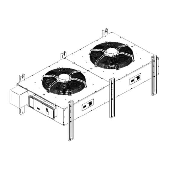
3. Mechanical Specifications The cabinet and legs are made of aluminum. In the multi-fan mod- els the air flow is maintained separated. The protection mask of copper pipe is used to protect the inlet and outlet copper pipes. The window is used to clear the heat exchanger periodically. The attaching legs are the same for horizontal and vertical instal- lation. -
Page 7: 4� Dimensions And Weights
4� Dimensions and Weights Note The installation holes are slot holes. Reference dimensions for vertical installation Tab�4-1 Weights Taking the double-fan condenser as an example, the dimension Coil for vertical installation is shown in Figure 4-2 on the right (bottom Circuits Weight Volume... -
Page 8: 5� Parameters Of Operating Environment
-35 °C ÷ +46 °C For installation with ambient temperature below -20°C be sure the plant has been Outdoor ambient temperature arranged with Low Temp kit and other necessary arrangement as per Vertiv speci- fication. Outdoor ambient humidity 5% ÷ 95% Do not use in explosive, acid or anyway aggressive atmosphere. -
Page 9: 8� Technical Data And Performances
8� Technical Data and Performances Tab� 8-1� Technical data Total Heat Air Vol- Noise Level Current Ab- Power supply Rejection Power Input sorption * R410A Model [dB(A)] [V/Ph/Hz] [kW] [m3/h] [kW] MCS028 230/1/50 29.60 7452 50.1 0.47 1.73 2.30 MCM035 230/1/50 34.50 8000... -
Page 10: 10� Installation Notes
10� Installation Notes Vertical installation. Remove the legs not necessary (See fig- ure 10-2) Fig� 9-2� Unpacking Fig� 10-1� Base area for vertical installation Condensers should be installed in a location offering maxi- mum security and access for maintenance. The service area must be respected Avoid areas prone to heavy snow or ice accumulations. -
Page 11: 11� Space Requirements
11� Space Requirements The condenser needs sufficient installation and service space around the installation place. The detailed space requirements are shown in Figure 11-1 and Figure 11-2. Fig� 11-1� Horizontal installation - space requirements Tab� 11-1 Space requirements Horizontal installation Vertical installation Model MCS028... -
Page 12: 12� Piping
12� Piping the cables, water leakage may occur at the waterproof joint. The cables cannot contact with hot objects, such as the copper pipe and water pipe without thermal insulation pipe, lest the insulation WARNING layers should be damaged. The protection tube or shielded line is required for the outdoor part of the connecting cable between the The units’... - Page 13 Fig� 13-1� Electrical box of Premium version - 1-2 fans Waterproof connector for Inlet Indoor Communication Cable Pressure transducer for circuit 1 Pressure transducer for circuit 2 Thermistor refrigerant circuit 1 Thermistor ambient 1 Thermistor refrigerant circuit 2 Thermistor ambient 2 Spare hole for project parallel connecting cable Cpu board / fan speed control board...
- Page 14 For CANbus network lengths • 460V wye with solidly grounded neutral and 277V line-to- greater than 107m, contact Vertiv for assistance. ground Premium Efficiency Control condenser are also designed to oper- Unacceptable Power Supplies - 380V to 460V Nominal Units ate with Terminals 700 and 710 wired to indoor unit compressor •...
- Page 15 Terminals are on the bottom of the disconnect switch • Remote unit shutdown—Replace exiting jumper between Ter- for three-fan and four-fan units. Three-phase service not by Vertiv. minals TB38-1 and TB38-2 with field-supplied normally closed See 14.1 - Wye vs. Delta Connection Power Supply.
-
Page 16: 14� Controller - Premium Fan
14� Controller - Premium fan This chapter introduces the application of the controller (including fan speed controller and communication board), which includes the definitions of wiring terminals, introduction of Human-Machine Interface (HMI) and operation of HMI. Note This chapter is mainly for the factory maintenance personnel. It is recommended that users should not operate the controller unless necessary. - Page 17 Silk print Definition Definitions of terminal pins Pin 1: COMM terminal of common alarm relay Pin 2: normally-open contact of common alarm relay Pin 3: normally-closed contact of common alarm relay TB74 Output terminal of common alarm Pin 4: COMM terminal of faulty shutdown alarm relay Pin 5: normally-open contact of faulty shutdown alarm relay Pin 6: normally-closed contact of faulty shutdown alarm relay Pin 1: high level of CAN port...
- Page 18 14�3 Indicators There are three indicators on the controller CPU board, as shown in Figure 14-1. The indicator functions are given in Table 14-3. Tab� 14-3� Functions of indicators on the controller CPU board Silk print Definition Color State Functions The 3.3V power supply of the controller is normal Power indicator Yellow...
-
Page 19: Initial Screen
14�4�3� Analog Signals Menu Description In analog signals menu “F―”, press ENT key to enter its items. The information of analog signal items includes condenser pressure, temperature and EC FAN actual speed. The display mode is that the item ID and signal value are displayed alternatively. The operation and item structure of analog signals menu are shown in the following figure. -
Page 20: Active Alarms Menu
14�4�4� Active Alarms Menu Description In active alarms menu “A―”, press ENT key to enter its items. The active alarm item displays all the active alarms of condenser. When there is an active alarm, the alarm information ID will be directly displayed. When there is no alarm, “-” is displayed. When there are multi alarms, the alarm information IDs will be displayed according to the time sequence, that is, the latest alarm will be displayed first. - Page 21 C—— Use UP and DOWN to change value success failure DOWN … … The meanings of the items of configuration menu are given in following table: Default (*) Item ID Meaning Notes Metric Imperial EBM EC FAN address EC FAN address ranges from 1 to 4, starting from 1. For instructions on these menu items see Appendix 3.
- Page 22 Default (*) Item ID Meaning Notes Metric Imperial EC FAN minimum speed for Lee Temp Refrigerant temperature set point 1 2.78 °C 37. 0 °F Refrigerant temperature set point 2 2.78 °C 37. 0 °F EC FAN1 request speed EC FAN2 request speed These values can be manually set only when system control state (C24) is Manual.
- Page 23 Item ID Meaning Default Notes Number of 1 – Single Circuit circuits 2 – Dual Circuit Lee Temp 0 – No Lee Temp installed option 1 – Lee Temp installed 0 – Small Condenser 1 – Medium size 2 – Large Note1 Alarm Information Alarm ID...
- Page 24 Alarm Information Alarm ID Meaning Possible Cause Handling Method 1. EC FAN is locked. For cause 1, check if EC FAN is locked. (1-4) 00 EC FAN high link current 2. EC FAN is damaged. For cause 2, replace EC FAN (1-4) 01 EC FAN drive error EC FAN is damaged.
-
Page 25: 15� Controller - Basic Fan
15� Controller – Basic fan 15�1 One phase power supply FACTORY SETTING COMPONENT OPERATION HOW TO SET SETTAGGIO DI COMPONENTE FUNZIONAMENTO COME TARARE FABBRICA PROG. DEFAULT VALUE 100% 230 V~ VALORE DI DEFAULT The fan speed controller is factory preset SET 1 = 23.4 barg at the default set point value (set point 1 = DIFF 1 = 5.4 barg... - Page 26 Fan operation is monitored so as to control the condensing pressure. This is done using the continuous fan speed controller. This is a factory installed device, the controller arrives already installed, cabled and set by the manufacturer Vertiv. Consult the RDM300 kit manual also...
- Page 27 Configuration regulator RDM300 D.S. Procedure of configuration changing To change configuration proceed as below specified: 1- Press, and keep pressed, button SB1 (see 2.2); 2- Press simultaneously, and keep pressed, buttons: ENT and positioned below the display; 3- Release button SB1; 4- Wait until “Configuration Default Choice”...
- Page 28 Tab� 2� - Displayed Parameters DGT1 Default Values Displayed parameters description Set A Set B U�M� Selected Input value (with DGT-1 : value after Digital Scroll filter) Input N°1 value Input N°2 value (FIX 1 = °C; FIX 2 = bar) °C / bar Set-point (bar) 30.4...
- Page 29 • DGT-1 mode Connection of the 4-20mA transducer for the regulation, and the NTC probe for the MIN speed selection. Code Sensor Type Range Transducer 4-20mA 0-45 bar DGT-1 Probe NTC 10kohm -10÷60°C • FIX-2 mode Connection of the 4-20mA transducers for the regulation of two circuits (the higher in value drive the fans). Code Sensor Type...
-
Page 30: 16� Maintenance And Troubleshooting
In parallel with the function regulator, acting permanently the following checks: If the instantaneous pressure input IN1 (and/or IN2) exceeds the “Sh” value, the output immediately goes to 100%.It comes under the control characteristic when the input falls below the value “Sh - ih”. Use the unfiltered input signal, regardless of the mode FIX or DGT selected. - Page 31 2. Clean the heat exchanger with water, compressed air or fin de- board is installed inside the electrical control box). tergent (weakly alkaline). The direction of inverse air flow is pref- 3. Remove all the cables connected with the controller board. erable.
-
Page 32: Annex I - Application Firmware Update
Annex I – Application Firmware Update NOTE: The configuration of the board is reset to factory defaults after firmware update. The configuration must be manually restored. Update of the condenser board firmware is accomplished using a USB flash drive mounted on the board’s USB port (P54). Here are the steps necessary to update firmware. -
Page 33: Annex Ii - Overall Dimensions
Annex II – Overall Dimensions MCS 028 1180 1283... - Page 34 MCM 035 1269 1381...
- Page 35 MCM 040 1269 1381...
- Page 36 MCL 055 1509 1676 1068...
- Page 37 MCM 070 2602 1269 2038...
- Page 38 MCM 080 2602 1269 2038...
- Page 39 MCL 110 3102 1509 2493...
- Page 40 MCM 160 5045 1269 2038 2038...
- Page 41 MCL 165 4527 1509 2493 1426...
-
Page 42: Annex Iii - Packaging Dimensions And Weights
Annex III – Packaging Dimensions and Weights Wooden Crate std Seaworthy packing Weight Packaging Drawing Model P/N Seaworthy Wood weight (Kg) weight Seaworthy (mm) (mm) (mm) Packing (mm) (mm) (mm) (kg) (*) (kg) Packing MCS028 1430 1250 1125 244582 VC374 1900 1700 1540... - Page 43 Fabrikant - - Producent Κατασκεναστηζ Vertiv S.r.l. - Zona Industriale Tognana Via Leonardo da Vinci, 16/18 - 35028 Piove di Sacco - Padova (Italy) Il Fabbricante dichiara che questo prodotto è conforme alle direttive Europee: The Manufacturer hereby declares that this product conforms to the European Union directives: Der Hersteller erklärt hiermit, dass dieses Produkt den Anforderungen der Europäischen Richtlinien gerecht wird:...
- Page 44 Leonardo Da Vinci 16/18, Zona Industriale Tognana, 35028 Piove di Sacco (PD) Italy, Tel: +39 049 9719 111, Fax: +39 049 5841 257 © 2016 Vertiv Co. All rights reserved. Vertiv, the Vertiv logo and Vertiv Liebert MC are trademarks or registered trademarks of Vertiv Co. All other names and logos referred to are trade names, trademarks or registered trademarks of their respective owners.
Need help?
Do you have a question about the Liebert MC and is the answer not in the manual?
Questions and answers