
Related Manuals for Honeywell fiplex HONBDA-EA


Summary of Contents for Honeywell fiplex HONBDA-EA
- Page 1 English HONBDA-EA Dual Band VHF & UHF Digital Signal Boosters High Power User Manual UM-1065/ Rv.03...
-
Page 2: Document History
Document History Description Revision Date Issued Original Version Sept 16th, 2020 General Review Nov 24 , 2020 General Review Nov 11 , 2021... -
Page 3: About This Manual
This manual describes installation, commissioning, operation and maintenance of Fiplex by Honeywell VHF & UHF Dual Band Signal Booster High Power and Fiplex Control Software (FCS). The first part of the manual describes the Signal Booster hardware and the second part describes the software. - Page 4 Abbreviations Automatic Gain Control Base Station, BS antenna = towards the base station Direct Current Downlink signal direction (from base station via Signal Booster / Master / Remote to mobile station) DPLX Duplex filter EEPROM Electrical Erasable Programmable Read Only Memory ETSI European Telecommunications Standard Institute Fiplex Control Software...
-
Page 5: Safety Guidelines
Failure to comply with these precautions or specific warnings elsewhere in the manual violates safety standards of design, manufacture, and intended use of equipment. Fiplex by Honeywell assumes no liability for the customers failure to comply with these requirements: • Grounding – These DAS Master Unit/Signal Boosters must always be operated with the ground wire properly connected. -
Page 6: Safety Notices
Fiplex by Honeywell assumes no liability for the customer's or user's failure to comply with these requirements: • Avoid explosive atmospheres - To avoid explosion or fire, do not operate this product in the presence of flammable gases or fumes. -
Page 7: Fcc Compliance
FCC Compliance CAUTION: If the user selects a filter with a bandwidth greater than 75KHz, then the following label should be applied to the unit: ATTENTION: This device complies with Part 15 of the FCC rules. Operation is subject to the following two conditions: (1) this device may not cause harmful interference and (2) this device must accept any interference received, including interference that may cause undesired operation. -
Page 8: Product Description
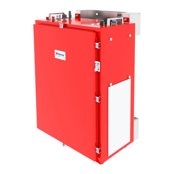
1. Product Description The VHF & UHF BDA are an FPGA based VHF and UHF Dual Band Signal Booster that transmits in the Downlink frequencies of 136-174 & 450-512MHz and receives in the Uplink frequencies 136- 174MHz & 450-512MHz for United States and Canada. Each band has a separate intermediate filtering. - Page 9 1.1 Product ports 1.2 Dimensions Dimensions in mm (in)
-
Page 10: Power Specifications
NOTE: The AC version of this device must be connected to an annunciator that provide visual and audible alarms complying with the UL2524 standard. This can be: - The Fiplex by Honeywell HONBDA-BTTY-100100 or the HONBDA-BTTY-100050. - Or any other Annunciator complying with the UL2524 standard. - Page 11 CAUTION: This equipment is designed to permit the connection of the earthed conductor to the DC supply circuit to the earthing conductor of the equipment. If this connection is made, all the following conditions must be met: • This equipment shall be connected to the DC supply system earthing electrode conductor or to a bonding jumper from an earthing terminal bar or bus to which the DC supply system earthing electrode conductor is connected.
-
Page 12: Mechanical Specifications
1.4 Mechanical Specifications Parameter Specifications Notes 34.17 x 24.9 x 18 in 868.15 x 633.6 x 459.45 mm Size Weight Aprox 77 lbs - 35kg Donor/Coverage Antenna Matting Male Connector Torque 3.7 Connectors Ports: N (f) ft.lbs. AC Power in AC cord Dedicated two pole circular DC (Battery) Power In... -
Page 13: Environmental Specifications
1.5 Environmental Specifications Parameter Specifications Notes Operating Temperature -25º C to +55ºC (ambient) -13º F to +131º F Storage Temperature -40º C to +60ºC (ambient) -40ºF to + 140ªF Operating Humidity 5% to 95% Environmental IP-67, NEMA 4 compliance 1.6 Alarm Indicators There is an indicator panel located at bottom of the Signal Boosters. -
Page 14: Installation
2. Installation Mounting the DAS Master/Signal Booster This device is designed for outdoor usage with a weatherproof outdoor NEMA4 cabinet that can be mounted without any kind of shelter from rain, snow or hail. However, to improve reliability, it is recommended to mount this device on a site with shelter from direct exposure to sun, rain, snow and hailing. - Page 15 Step 2 Step 3...
- Page 16 Step 4...
-
Page 17: Important Installation Guidelines
Important Installation Guidelines The following guidelines should be carefully observed for all installations of VHF & UHF series. • The unit shall be installed by QUALIFIED SERVICE PERSONNEL only. • This device shall be installed in a restricted access location. •... - Page 18 • The signal booster must be connected to ground for protection. • Fiplex by Honeywell recommends that installers not wear jewelry or metal accessories when installing this signal booster. • Do not place cables or tools that may damage the signal booster in proximity to it.
-
Page 19: Connection Step By Step
3. Commissioning 3.1 Connection step by step 1. Connect the TX Service antennas to the To Mobile RF DL Output port. N type female connectors are used in the Signal Booster. 2. Connect the RX Service antenna to the To Mobile RF Input port. N type female connectors are used in the Signal Booster. - Page 20 7. Connect the multipin dry contact connector to access to the dry contact alarms. 8. Once the Signal Booster has been connected to the power source, it takes about 40 seconds to run a booting routine. After that time, the Signal Booster is ready to be connected via USB cable to a computer running Fiplex Control Software (FCS) to be properly configured.
- Page 21 NOTICE TO USERS, INSTALLERS, AUTHORITIES HAVING JURISDICTION, AND OTHER INVOLVED PARTIES This product incorporates field-programmable software. In order for the product to comply with the requirements in the Standard for In-building 2-Way Emergency Radio Communication Enhancement Systems, UL2524 certain programming features or options must be limited to specific values or not used at all as indicated below.
- Page 22 Relay 1, 2, 3 or Enable/Disable - Assigned to Laser Fail Enabled - Assigned to Relay 4 Relay 1, 2, 3 or Enable/Disable - High Assigned to Temperature Enabled - Assigned to Relay 4 Relay 1, 2, 3 or Alarm Oscillation Assigned to Detection...
- Page 23 The setting will vary from site to site, users must follow these instructions: - For Minimum TX Power for VSWR Detection: This feature is to avoid fake alarms, the user has to make sure that the indicated "Power Forward" is above the configured "Minimum TX Powe for VSWR detection"...
- Page 24 150KHz, 11.5μS 100KHz, 13.5μS To comply with P25 PH2 delay requirements the 75KHz, 16.0μS user must do the filtering selection ONLY with the 62.5KHz, following options: Filter BW and 18.0μS 150KHz, 11.5μS Delay 50KHz, 21.0μS 100KHz, 13.5μS Selection 37.5KHz, 75KHz, 16.0μS 25.5μS 62.5KHz, 18.0μS 25KHz, 35.0μS...
- Page 25 WARNING: The Antenna ports of this device should be protected with a surge arrestor that provides a maximum resistance of 5.2 MOHM (including tolerance) and minimum wattage rating of 1/2W between the antenna port and ground.
-
Page 26: Wiring Diagram
4. Wiring Diagram 4.1.1 AC Version MAIN AC SUPPLY CIRCUIT: 110VAC / 60Hz, 130W max. These Signal Boosters must always be operated with the ground wire properly connected. The External Main Earth terminal shall be connected to the Building Main Earth. - Page 27 4.1.2 AC Wiring Stub Assembly Procedure MAIN AC SUPPLY CIRCUIT: 110VAC / 60Hz, 200W max. AC Wiring Stub Final Assembly...
- Page 28 4.2 DC Version 24 VDC to -48VDC MAIN DC SUPPLY CIRCUIT: , 130W max.
-
Page 29: Dry Contacts
Dry Contacts Pinout Pin 1-2: Relay 1 Pin 3-4: Relay 2 Pin 5-6: Relay 3 Pin 7-8: Relay 4 Relay Pre-Assignment: Relay 1: Donor Antenna Malfunction Relay 2: VSWR Relay 3: Donor Antenna Disconnection Relay 4: General Failure Users must use the provided connector to assemble the dry contact connections as indicated above. - Page 30 To install the EOLR on the Signal Booster dry contacts, open the BDA lid and locate the relay module containing relays R1, R2, R3 and R4. To operate this Signal Booster with the Fiplex by Honeywell Battery Backup, 10K end of line resistors must be installed in the terminal block as indicated in the following image:...
-
Page 31: Starting Operation
5. Starting Operation BE SURE THAT “TO MOBILE” AND “TO BASE” PORTS ARE PROPERLY LOADED EITHER WITH 50 OHMS DUMMY LOADS, OR RADIATING SYSTEM. IN ALL MASTER UNITS AND REMOTE UNITS. 1. Turn ON the Master Unit and Remote Unis coupled together, connect computer to the Master Unit through USB cable, and run Fiplex Control Software. - Page 32 3. If channel filtering is required, turn ON the needed channel filters set the desired frequencies and bandwidths. 4. If adjustable bandwidth filtering is required, turn On the Adj.Bw filters and setup the start and stop frequencies in the following part of the GUI.
- Page 33 5. If OFF, Turn ON the UL and DL power amplifiers, and check that any alarm indicator is active. 6. Setup desired operating gain using FCS. UL and DL chain are independent, so both values must be set. To set DL band gain is recommended that AGC works around 3 - 6dB in each channel, in this way, maximum output power is achieved.
- Page 34 8. Setup desired filter bandwidth, depending on presence of adjacent channels. The wider the filter the lower the added delay, but if adjacent signal is detected, narrow filters can be used. Spectrum analyzer of FCS can be used to know rejection to undesired signals. It is recommended that adjacent channels output power be, at least, 10dBc lower than useful carrier.
-
Page 35: Laboratory Measurements
Laboratory Measurements For specific parameters verification and laboratory tests, please contact factory. Detailed procedures, recommended tests set up, and a knowledge engineering team will bring adequate support to perform the measurements in a comfortable and safely way. - Page 36 Part 2 Software 1. Introduction Fiplex Signal Booster can be fully configured and monitored in local and remote mode. Local mode: USB port with Windows desktop application Remote mode: Remote Web server In following section, each control mode (configuration / monitoring) are described. 2.
- Page 37 3. The installer will start to copy the necessary files.
- Page 38 4. After installation has completed, a shortcut in user desktop will appear. 5. Connect USB cable between computer and Signal Booster, keeping the Signal Booster powered off. Usually, drivers will be automatically installed, but depending on Windows version, screen asking for drivers of new device can appear. Drivers can be found in application folder: C:\Program Files (x86)\FiplexControlSoftware\drivers”.
- Page 39 7. Execute the Fiplex Control Software. Next window will appear: User interface controls: Scan Devices Button: refresh the available COM ports and identify Fiplex devices Connection Button: connect / disconnect software from Signal Booster List of available devices: below two buttons, is placed a dropdown list that shows all available COM ports.
- Page 40 Now, the Fiplex Digital Signal Booster is shown in the list of available devices, and connection button is enabled. NOTE: Fiplex Signal Booster could not appear in list, if COM port number is higher than COM16, depending on Windows version. COM port number can be forced to arbitrary number (below COM16) through Device Administrator.
- Page 41 Change COM port number 9. Click “Connect”. Fiplex Control Software window will be automatically maximized, and web browser will show the configuration screen. Application screens are described in the next section due to these application screens and web pages (in webserver remote mode) are the same. 10.
Need help?
Do you have a question about the fiplex HONBDA-EA and is the answer not in the manual?
Questions and answers