Table of Contents
Advertisement
Advertisement
Table of Contents

Related Manuals for FUTABA 6YG-FM


Summary of Contents for FUTABA 6YG-FM
- Page 2 •The contents of this manual are subject to change without prior notice. •This manual has been carefully written. Please write to Futaba if you feel that any corrections or clarifications should be made. •Futaba is not responsible for the misuse of this product.
-
Page 3: Table Of Contents
SAFETY INFORMATION............4 Meaning of Special Markings ............4 Precautions During Flight ............4 NiCd Battery Charging Precautions ..........6 Storage and Disposal Precautions ..........7 Other Precautions ................8 BEFORE USE ..............9 Set Contents ................9 Name and Handling of Each Part..........10 Transmitter Operation and Movement of Each Servo ....14 INSTALLATION AND ADJUSTMENT ........15 Connections ................15 Adjustments ................17... -
Page 4: Safety Information
NFORMATION AFETY To ensure safe use, observe the following precautions. Meaning of Special Markings Pay special attention to safety at the parts of this manual that are indicated by the following marks. Mark Meaning Procedures which may lead to a dangerous condition and cause death or serious injury to the user if not carried out properly. - Page 5 Do not fly in the following places: -Near other R/C flying fields (within about 2.5miles [3km] -Near people on the ground, or objects in the air -Near homes, schools, hospitals, or other places where there are a lot of people -Near high tension lines, high structures, or communication facilities Radiowave interference and obstructions may cause a crash.
-
Page 6: Nicd Battery Charging Precautions
Turning on the power switch: Set the transmitter (Tx) throttle stick to idle. 1. Turn "On" the transmitter (Tx) power switch, 2. Then turn "On" the receiver (Rx) power switch. Turning off the power switch: Stop the engine, 1. Turn "Off" the receiver (Rx) power switch, 2. -
Page 7: Storage And Disposal Precautions
Do not short the nicd battery connector terminals. Shorting the terminals will cause sparking and overheating and result in burns or fire. Do not drop or apply strong shock to nicd battery. The battery may short out and cause overheating or breakage and electrolyte leakage and result in burns or damage from chemical contents. -
Page 8: Other Precautions
Do not get fuel, oil, etc. on plastic parts. The plastic may melt, discolor, become brittle and fail to function. Always use Genuine Futaba transmitters, receivers, servos, ESCs, nicd batteries, and other optional parts. Futaba is not responsible for damage, etc. caused by the use of parts other than Genuine Futaba parts. -
Page 9: Before Use
EFORE Set Contents After opening the carton, first check if the following items are provided. The set contents depend on the type of set, and these are the standard. Transmitter T6YG Receiver R147F R127DF Servo S3003 (x4) Servo horns Receiver switch Extension cord Small screwdriver and others... -
Page 10: Name And Handling Of Each Part
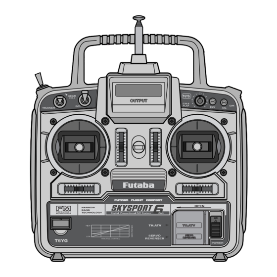
Name and Handling of Each Part Transmitter T6YG (Front Panel) Antenna /Aerial Carrying handle Elevator/Aileron Voltage indicator Dual Rate switch (ELV/AIL D/R) Landing gear switch (Ch.5) Channel 6 Elevator D/R Aileron D/R Trainer switch Throttle (Mode 2) /Rudder stick Elevator (Mode 2) /Aileron stick Elevator trim lever Throttle trim... - Page 11 Landing gear switch: Controls the raising and lowering of retractable landing gear. Not all models will use this function. Flap knob: Controls the flap servo(CH6). Dual Rate switch (AIL. D/R/ELV. D/R): Dual Rate trimmers (AIL./ELV.): Used to set to reduce the servo travel by flipping each Dual Rate switch. The travel reduction for the aileron and elevator may be set by each trimmer.
- Page 12 Do not charge Dry Batteries. Charging dry batteries will cause overheating or breakage and electrolyte leakage and result in burns or damage by the chemical content. Charging the Nicad Battery Never plug the special slow charger into an AC outlet other than the voltage specified shown on the charger.
- Page 13 Receiver R127DF/R147F "7": Not Used (CH7) "6": Flap servo (CH6) Antenna "5": Gear servo (CH5) "4": Rudder servo (CH4) "3": Throttle servo (CH3) "2": Elevator servo (CH2) Crystal "1": Aileron servo (CH1) "B" Battery Connector Crystal: The crystal is installed at the side of the receiver. Servo S3003 Servo wheel Mounting flange...
-
Page 14: Transmitter Operation And Movement Of Each Servo
Transmitter Operation and Movement of Each Servo Before making any adjustments, learn the operation of the transmitter and the movement of each servo. (In the following descriptions, the transmitter is assumed to be in the operating state.) Aileron Operation When the aileron stick is moved to the right, the right aileron is raised and the left aileron is lowered, relative to the direction of flight, and the plane turns to the right. -
Page 15: Installation And Adjustment
NSTALLATION AND DJUSTMENT This section describes the installation and adjustment of the receiver, servos, etc. to the plane. Connections Connection examples are shown below. Connection Example •Four servos are supplied as standard. -15-... - Page 16 (Connector Connection) Insert the receiver, servo, and battery connectors fully and firmly. If vibration, etc. causes a connector to work loose during flight, the plane may crash. (Receiver Vibration proofing / Waterproofing) Vibration proof the receiver and battery by wrapping them in sponge rubber or some such material.
-
Page 17: Adjustments
Adjustments The operating direction, neutral position, and steering angle of each servo are adjustable. The basic linkage and adjustments, control layout, and servo, Rx and Nicad installation should conform to the fuselage design drawings and kit instruction manual. Be sure that the center of gravity is at the prescribed position. Adjustment Procedure Before making any adjustments, set all the SERVO REVERSING switches on the front of the transmitter to the lower(NOR) position and set both Dual Rate... -
Page 18: Using Other Functions
SING THER UNCTIONS Aileron/Elevator Dual Rate (D/R) Function The maximum travel of the aileron and elevator servos can be altered by operating the dual rate switch. For instance, when the switch is in the lower position, the deflection angle is the normal deflection angle. The normal deflection angle, at the low switch position, can be adjusted by the dual rate trimmers (AIL/ELV). -
Page 19: Stick Lever Spring Tension Adjustment
Stick Lever Spring Tension Adjustment The operating feel of the aileron, elevator, and rudder sticks can be individually adjusted by adjusting the stick spring tension. 1. Remove the four transmitter rear case screws and carefully remove the rear case. 2. Adjust the spring tension by turning the screw of the channel you want to adjust (clockwise to stiffen counter-clockwise to soften). -
Page 20: Reference
EFERENCE Ratings Transmitter T6YG Receiver R127DF (2 sticks, 6 channels, FM transmitter) (7 channels, FM receiver) Transmitting frequency: 29, 35, 36, 40, 41, 50, Receiving frequency: 50, 72, or 75 MHz 60, 72, or 75 MHz Intermediate frequency: 1st IF 10.7MHz 2nd IF 455kHz Modulation method: FM(Frequency Modulation) Power requirement: 6V (penlight battery x4), 4.8V or 6v NiCd... -
Page 21: Troubleshooting
If your R/C set does not operate, its range is short, it intermittently stops operating, or it operates erroneously, take the action shown in the table below. If this does not correct the trouble, please contact a Futaba dealer. Check point... -
Page 22: Glossary
EFERENCE Glossary The following defines the symbols and terms used in this instruction manual. Aileron (AIL) Control surface on the left and right sides of the Servo horn main wing of an aircraft. It usually controls A part that is installed to the shaft of a servo banking of the aircraft. -
Page 23: Repair Service
• Model Numbers and Quantity • Your Name, Address, and Telephone Number. 1610 Interstate Dr. Champaign, IL 61822 (217) 398-0007 FUTABA CORPORATION Makuhari Techno Garden Bldg., B6F 1-3 Nakase, Mihama-ku, Chiba 261-8555, Japan Phone: (043) 296-5118 Facsimile: (043) 296-5124 -23-...
Need help?
Do you have a question about the 6YG-FM and is the answer not in the manual?
Questions and answers