Advertisement
PRODUCT DESCRIPTION
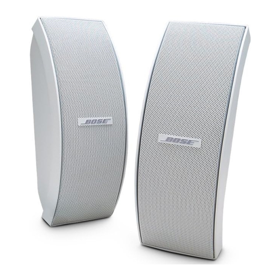
The Bose 151SE Environmental Speaker offers an advanced design with quality construction. Each loudspeaker contains three 1.4 ohm environmentally resistant Twiddler speakers in a horizontal arc-shaped 2.2 liter ported enclosure. A protection and equalization circuit is located on the pcb attached to the rear half of the speaker. The speaker has an aluminum grille with a logo which rotates in 90 degree increments. The 151SE is available in black and white.
SPECIFICATIONS
| Transducers: | Three 2.5" environmental Twiddler speakers per enclosure | |
| Impedance: | 6 Ohms nominal (4.8 Ohms minimum) 20-20kHz | |
| Power Handling: | 50 W (17.3Vrms) continuous per IEC-268-5 Recommended amp/receiver power 10-100W per channel | |
| System Protection: | PTC in parallel with a capacitor | |
| Sensitivity: | 89.5dB SPL at 2.83V, 1meter, 2kHz-octave band | |
| Flux Leakage: | N/A, not shielded; not for use near a video monitor | |
| External Dimensions: | 12.3" x 4.5" x 6.2" (31.2cm x 11.4cm x 15.8cm) | |
| Weight: | Single Speaker: | 4.6lb. (2.1 kg) |
| Packed Pair: | 11.7 lb. (5.3 kg) | |
PART LIST NOTES
- This part is not normally available from Customer Service. Approval from the Field Service Manager is required before ordering.
- The individual parts located on the PCBs are listed in the Electrical Part List.
![burn hazard]() This part is critical for safety purposes. Failure to use a substitute replacement with the same safety characteristics as the recommended replacement part might create shock, fire and/or other hazards.
This part is critical for safety purposes. Failure to use a substitute replacement with the same safety characteristics as the recommended replacement part might create shock, fire and/or other hazards.- This part is referenced for informational purposes only. It is not stocked as a repair part. Refer to the next higher assembly for a replacement part.
 This part is critical for safety purposes. Failure to use a substitute replacement with the same safety characteristics as the recommended replacement part might create shock, fire and/or other hazards.
PACKAGING PART LIST

See Figure 1.
| Item Number | Description | Part Number | Qty. | |
| 1 | CARTON, RSC, 17.00X14.19X7.25, C | 294090 | 1 | |
| 2 | PACKING, EPS, TOP/BOTTOM, 151 II | 273823-01 | 2 | |
| 3 | BRACKET, SINGLE, KIT, BLK, UV | 315948-004 | 2 | |
| BRACKET, SINGLE, KIT, WHT, UV | 315948-005 | |||
| 4 | GUIDE, OWNERS, 151 II | 273809 | 1 | |
| 5 | CARD, REGIST. AND WARRANTY | 262933 | 1 | |
| 6 | BAG, POLY, 14.38x9.87x2 mil | 103351 | 1 | |
| 7 | COMMITMENT LETTER | 251001 | 1 | |
| 8 | HARDWARE KIT, 151 SE | 292523-002 | 1 | |
| 9 | BAG, POLY, 16X18 | 253804 | 2 | 4 |
MAIN PART LIST

See Figure 2.
| Item Number | Description | Part Number | Qty. | Note |
| 1 | LOGO, BLACK | 273812-01 | 1 | |
| LOGO, WHITE | 273812-02 | |||
| 2 | TAPE, FOAM, .06 THK | 277053-001 | 2 | 4 |
| 3 | GRILLE, ALUM, BLACK | 273810-01 | 1 | |
| GRILLE, ALUM, WHITE | 273810-02 | |||
| 4 | FOAM, LOGO | 275803-001 | 1 | |
| 5 | RING, RETAINER, LOGO | 275804-001 | 1 | |
| 6 | ENCLOSURE, BAFFLE, BLACK | 274260-001 | 1 | 4 |
| ENCLOSURE, BAFFLE, WHITE | 274260-002 | |||
| 7 | TWIDDLER, 60MM, ENVIR., 1.4 OHM | 273543-002 | 3 | |
| 8 | CONNECTOR, ENVIR, BLK | 250815-01 | 1 | |
| 9 | CONNECTOR, ENVIR, RED | 250815-02 | 1 | |
| 10 | ENCLOSURE, BACK, BLACK | 274261-001 | 1 | 4 |
| ENCLOSURE, BACK, WHITE | 274261-002 | |||
| 11 | SCREW, TAPP, 8-11X.75, PAN, ASY, SQ | 296495-012 | 8 | |
| 12 | SCREW, TAPP, 6-13X.500, PAN, AS, SQ | 296443-008 | 2 | |
| 13 | CROSSOVER PCB ASSY, ROHS | 289945-001 | 1 | |
| 14 | INSERT, NUT, DECORATIVE CAP | 123991 | 2 |
CROSSOVER PART LIST

See Figure 3.
| Reference Designator | Description | Part Number | Note |
| R1 | RES, WW, 5W, 10%, 2.7 OHM | 132105-2R7 | 4 |
| R2 | JUMPER, 22AWG, INSUL, 1.25" | 108435-1R25 | 4 |
| C1 | 47uF, EL, BP, 63V, 20% | 283940-470A | 4 |
| C2 | 470uF, EL, BP, 85C, 20% | 268841-471H | 4 |
| C3 | 100uF, EL, BP, 85C, 20% | 268841-Z101H | 4 |
| L1 | INDUCTOR ASSY, 200uH, ROHS | 291571-001 | 4 |
| J1 | PIN, GROOVED, .52x.34x.045 | 291521-5234 | |
| J2 | PIN, GROOVED, .52x.34x.045 | 291521-5234 | |
| PTC1 | POLYSWITCH, 60V, RXE065 | 275782 | |
| PTC2 | JUMPER, 22AWG, INSUL | - | 4 |
| - | PC BOARD, MODEL 191 | 267563-002 | 4 |
| - | TAPE, FOIL | 140551 | 4 |
| - | RIVET, ANCHOR, PLASTIC, 2-PIECE | 250072-001 | 4 |
DISASSEMBLY PROCEDURES
- Grille Removal
- Remove the grille by pulling on the ends with your fingers, or pry carefully with a nonmetallic object.
Note: The grille is made entirely of metal. Do not try to remove the grille by pulling on the plastic (polypropylene) speaker enclosure.
- Remove the grille by pulling on the ends with your fingers, or pry carefully with a nonmetallic object.
- Enclosure Disassembly
- To disassemble the enclosure, place the unit on a flat soft surface grille side down. Remove the 8 screws identified below.
Note: The unit is press-fit together. All parts of the unit must be in place prior to replacing the 8 screws.

- With the unit face down, gently pull up on the rear enclosure. Be careful not to lift the unit too high, as the Twiddler speakers are wired to the rear enclosure. Lay the rear enclosure on its side to expose the inside of the unit and the Twiddler speakers as seen below.
Note: There are no screws in the Twiddler speakers, they are held in place by the press fit between the rear enclosure and the baffle.

- To disassemble the enclosure, place the unit on a flat soft surface grille side down. Remove the 8 screws identified below.
- Crossover PCB Removal
- Perform Procedure 1.
- Remove the 2 screws identified below that secure the crossover assembly to the cabinet.

- Make a note of the wiring configuration. Lift out the crossover PCB and cut the wires asclose to the terminals as possible.

- Twiddler Removal
- Perform procedure 1.
- Make a note of the wiring configuration. Lift the Twiddler speakers out and cut the wires as close to the wire terminals as possible.

- Twiddler Replacement
- Set the center Twiddler speaker in place first, then the two outer Twiddler speakers. Take care to lower the outer Twiddler speakers straight down when setting them in place, this will ensure that the gasket seats in the correct location.
- Wire the Twiddler speakers as shown below.

- Enclosure Re-assembly
- Re-install the Crossover PCB. Connect the PCB as shown in the wiring diagram and the schematic diagram.
- With the baffle face down, lower the enclosure over the baffle. Dress the foamed wires toward the center of the loudspeaker enclosure.
Note: Ensure there are no wires visible through the speaker port once assembled. - Reinsert the 8 screws that secure the enclosure to the baffle assembly.
- Perform the test procedures in this manual to ensure that there are no air leaks or wire buzzes before returning the speaker to the customer.
- Grille Replacement
- Align the grille to the speaker enclosure and push in lightly.


TEST PROCEDURES
- Air Leak Test
- Apply an 8Vrms, 105Hz signal to the speaker input terminals.
- Listen to the front of the speaker carefully for air leaks from around the cabinet seams, and Twiddler speakers. Turn the speaker over and listen for air leaks from the enclosure securing screws and drivers.
- Sweep Test
- Apply a 6Vrms Vrms, 10Hz signal to the speaker input terminals.
- Sweep the signal generator from 10Hz to 3kHz and then back to 10Hz.
- Listen carefully for buzzes, ticks, rattles or other noises. Replace the Twiddler speakers if they are found to be defective.
Note: To distinguish between normal suspension noise and rubs or ticks, slightly displace the cone of the twiddler with your fingers. If the noise can be made to go away or get worse, it is a rub or tick and the twiddler should be replaced. If the noise stays the same, it is normal suspension noise and the twiddler is okay. Suspension noise will not be heard with program material.
Bose Corporation
The Mountain
Framingham, Massachusetts USA 01701
Reference Number 273701 REV. 01 7/2008
http://serviceops.bose.com
Documents / Resources
References
Download manual
Here you can download full pdf version of manual, it may contain additional safety instructions, warranty information, FCC rules, etc.
Advertisement


Need help?
Do you have a question about the 151SE and is the answer not in the manual?
Questions and answers