Table of Contents
Advertisement
Quick Links
00_Cover
Downloaded from
www.Manualslib.com
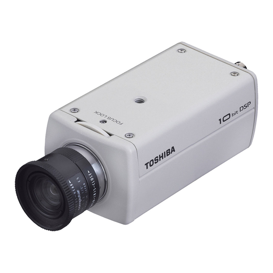
CCD COLOR CAMERA
IK-6210A/IK-6410A
Please read this manual thoroughly before use, and keep it handy
for future reference.
TABLE OF CONTENTS
IMPORTANT SAFEGUARDS ........................................ 2
1. FEATURES AND DESCRIPTION ................................. 4
2. COMPONENTS ............................................................ 4
3. PART NAMES AND FUNCTIONS ................................ 5
4. CAMERA INSTALLATION ............................................. 6
5. CONNECTIONS AND OPERATIONS .......................... 7
6. LENS ............................................................................ 9
7. LINE-LOCK PHASE ...................................................... 10
8. AUTOMATIC ELECTRONIC SHUTTER (AES) ............. 11
9. BACKLIGHT COMPENSATION (BLC) ......................... 11
10. NOTES ON USE AND INSTALLATION ........................ 12
11. IN CASE OF PROBLEMS ............................................ 12
12. SPECIFICATIONS ........................................................ 13
13. EXTERIOR VIEW ......................................................... 15
1
manuals search engine
INSTRUCTION MANUAL
Record in space provided below the Model # and
the Serial # as found on the label on the bottom of
this unit.
Model #
Serial #
Retain this information for future reference.
06.8.7, 11:08 AM
Advertisement
Table of Contents

Related Manuals for Toshiba 6410A - CCTV Camera


Summary of Contents for Toshiba 6410A - CCTV Camera
-
Page 1: Table Of Contents
INSTRUCTION MANUAL CCD COLOR CAMERA IK-6210A/IK-6410A Please read this manual thoroughly before use, and keep it handy for future reference. Record in space provided below the Model # and the Serial # as found on the label on the bottom of this unit. -
Page 2: Important Safeguards
IMPORTANT SAFEGUARDS 1. Read Instructions 13. Lightning All the safety and operating instructions should be For additional protection on this video product during read before the product is operated. a lightning storm, or when it is left unattended and 2. Retain Instructions unused for long periods of time, unplug it from the wall outlet and disconnect the power supply and cable The safety instructions and instruction manual should... - Page 3 • The CAUTION label, shown on the left, is attached on the camera. CAUTION TO REDUCE THE RISK OF ELECTRIC SHOCK. DO NOT REMOVE COVER (OR BACK). NO USER SERVICEABLE PARTS INSIDE. REFER SERVICING TO QUALIFIED SERVICE PERSONNEL. The lightening flash with arrowhead WARNING : symbol, within an equilateral triangle, TO REDUCE THE RISK OF FIRE OR...
-
Page 4: Features And Description
1. FEATURES AND DESCRIPTION 1. 24V AC/12V DC dual-voltage capable extends power choice. 2. Camera has the ability to automatically switch the display to color in daylight or black and white at night. 3. Camera synchronization mode is selectable between internal and line-lock. 4. -
Page 5: Part Names And Functions
3. PART NAMES AND FUNCTIONS - 5 - 01_p2-p32 06.8.7, 11:08 AM Downloaded from www.Manualslib.com manuals search engine... -
Page 6: Camera Installation
4. CAMERA INSTALLATION Wall 9.5 (0.37) Installation Example 1/4"-20UNC 112 (4.41) 15 (0.59) The Installation example is for reference only. Mounting bracket is not included. Dimensions : mm (inch) - 6 - 01_p2-p32 06.8.7, 11:08 AM Downloaded from www.Manualslib.com manuals search engine... -
Page 7: Connections And Operations
5. CONNECTIONS AND OPERATIONS Notes on connecting • Power plugs of connected equipment must be disconnected before camera installation. • A 75-ohm coaxial cable with connector (3C-2V or 5C-2V) is required for standard connection. • For details of wiring and operation of equipment to be connected, refer to their operation manuals. - Page 8 5-2. Line-Lock Control • Matching the vertical synchronization with the power frequency is called the Line-Lock. • This function is activated when the LL switch is set to ON. • When two or more cameras are switched by the video switcher for viewing by a monitor TV, the vertical sync.
-
Page 9: Lens
6. LENS Back-Focus Adjusment Back-Focus is adjusted at the factory to accommodate most standard lenses. Sometimes, slight adjustment to the camera back-focus is Focus Lock Screw necessary. Loosen the Focus Lock Screw. Achieve a clear image by rotating the focus ring. Tighten the Focus Lock Screw. -
Page 10: Line-Lock Phase
7. LINE-LOCK PHASE If two or more cameras within a system have different AC line phases are switched by the video switcher, the picture on the monitor TV will fluctuate vertically. Connect 24V AC input lines of all cameras so that they all share the same phase. -
Page 11: Automatic Electronic Shutter (Aes)
8. AUTOMATIC ELECTRONIC SHUTTER (AES) Exposure time is controlled automatically within a range of 1/60 sec. to 1/100000 sec. to obtain an adequate signal when the IRIS switch is moved to AES. When the back panel switch is turned to VIDEO or DC, the exposure time is fixed 1/60 sec. 9. -
Page 12: Notes On Use And Installation
10. NOTES ON USE AND INSTALLATION • Do not aim the camera at the sun Never aim the camera at the sun even with the camera power off. • Do not shoot intense light Intense light such as a spotlight may cause a bloom or smear. A vertical stripe may appear on the screen. -
Page 13: Specifications
12. SPECIFICATIONS IK-6210A Power 24V AC ~ ±10% 60Hz / 12V DC ±10% Power consumption 3.5W with Al lens Image sensor 1/3 inch CCD image sensor Image pickup area 0.194 inch (4.92 mm) horizontal x 0.145 inch (3.69 mm) vertical Effective picture element 510 horizontal x 492 vertical Scanning system... - Page 14 IK-6410A Power 24V AC ~ ±10% 60Hz / 12V DC ±10% Power consumption 3.5W with Al lens Image sensor 1/3 inch CCD image sensor Image pickup area 0.194 inch (4.92 mm) horizontal x 0.145 inch (3.69 mm) vertical Effective picture element 771 horizontal x 492 vertical Scanning system 2:1 interlace NTSC Standard TV system...
-
Page 15: Exterior View
13. EXTERIOR VIEW Dimensions : mm (inch) - 15 - 01_p2-p32 06.8.7, 11:08 AM Downloaded from www.Manualslib.com manuals search engine... -
Page 16: Limited Warranty
Product, if it does not perform as warranted. In order to take advantage of this Limited Warranty. You must: (a) call (877) 855-1349 to receive a RMA number: and (b) pay all transportation and insurance charges for shipment of the Product to the ASP or Toshiba Exchange Center.
Need help?
Do you have a question about the 6410A - CCTV Camera and is the answer not in the manual?
Questions and answers