Panasonic BL-C111A - Network Camera - Pan Operating Instructions Manual
Wireless/wired type
Hide thumbs
Also See for BL-C111A - Network Camera - Pan:
- Service manual (83 pages) ,
- Integration notes (11 pages) ,
- Installation manual (4 pages)
Table of Contents
Advertisement
Quick Links
BL-C111A
BL-C131A
Please read this document before using the product, and save this document for future reference.
Panasonic Network Camera Website: http://www.panasonic.com/netcam
for customers in the USA or Puerto Rico
BL-C131A (Wireless/Wired Type)
Model
Operating Instructions
Network Camera
BL-C111A (Wired Type)
Advertisement
Table of Contents

Related Manuals for Panasonic BL-C111A - Network Camera - Pan


Summary of Contents for Panasonic BL-C111A - Network Camera - Pan
- Page 1 Operating Instructions Network Camera BL-C111A BL-C111A (Wired Type) BL-C131A (Wireless/Wired Type) Model BL-C131A Please read this document before using the product, and save this document for future reference. Panasonic Network Camera Website: http://www.panasonic.com/netcam for customers in the USA or Puerto Rico...
-
Page 2: Main Features
Main Features On-site and remote camera monitoring Camera images can be monitored from a PC, both on-site and over the Internet. You can even use your mobile phone to view still images when you’re out of the house. MPEG-4 and Motion JPEG (MJPEG) support Live camera images can be viewed and recorded in both MPEG-4 and MJPEG formats, allowing you to select the video format that best suits your needs. - Page 3 Viewnetcam.com support After registering your camera with the Viewnetcam.com service, you can access the camera while away from home using an easy to remember Internet address of your choosing, such as bob.viewnetcam.com. For more information, see Page 75. Multi-language support The most commonly used camera pages can be displayed in English, French, German, Italian, Spanish, Russian, Simplified Chinese, Korean, and Japanese.
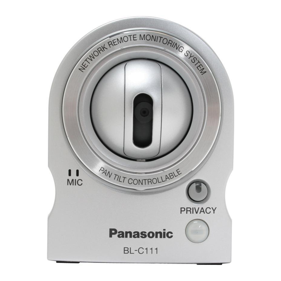
- Page 4 Other Information About this documentation • This manual is written for both the BL-C111A (Wired Type) and BL-C131A (Wireless/Wired Type). Available features and operations vary slightly depending on the model. You can confirm the model no. of your camera by checking the model no. printed on the front of the camera. •...
-
Page 5: Table Of Contents
Table of Contents 1 Camera Monitoring ..................7 Accessing the Camera ....................7 Viewing Live Camera Images ..................9 1.2.1 Using the Operation Bar ....................14 1.2.2 Aiming the Camera Lens ....................15 1.2.3 Limiting the Pan/Tilt Range ....................17 1.2.4 White Balance ........................18 1.2.5 Video Images (MJPEG and MPEG-4) and Image Refresh Rate ........19 1.2.6 Zooming .........................20 1.2.7... - Page 6 Setting the Date and Time ...................95 Changing Basic Camera Settings ................97 Changing Audio Settings ....................98 Changing Video Streaming Settings ................99 6 User Accounts ..................102 Understanding User Accounts ..................102 Changing the Administrator User Name and Password .........103 General Users ......................104 Guest Users ........................107 The Login Tab ......................109 7 Advanced Settings ................110 Changing Image Display Settings ................110...
-
Page 7: Camera Monitoring
1.1 Accessing the Camera 1 Camera Monitoring 1.1 Accessing the Camera You will need to know the following information to access the camera. • The camera’s IP address (e.g., 192.168.0.253) or URL (e.g., bob.viewnetcam.com) • The port number of the camera, if it is not 80. •... - Page 8 To confirm camera status and perform camera maintenance (see Page 119) To view URLs for Panasonic Network Camera support sites on the Internet (see Page 129) To log in to the camera as the administrator or as a general user (see Page 109) Click the desired display language Displays the camera’s model number...
-
Page 9: Viewing Live Camera Images
1.2 Viewing Live Camera Images 1.2 Viewing Live Camera Images Access the camera (see Page 7). Click the [Single] tab. • ActiveX® Controls must be installed in order to view MPEG-4 images, MJPEG images, or to use audio features. If the appropriate ActiveX Control is not installed, the camera will prompt you to install them. For more information see Page 11 or Page 12 depending on which operating system you are using. - Page 10 1.2 Viewing Live Camera Images Camera image (click an area of the camera image to use the click to center feature (see Page 15), or use your mouse to use the digital zoom feature (see Page 20) when displaying MJPEG video) Full-screen button (click to view the image in 4:3 full-screen mode;...
- Page 11 Windows XP Service Pack 2. Note • If ActiveX Controls cannot be installed, download them from the Panasonic Network Camera website (http://panasonic.co.jp/pcc/products/en/netwkcam/). When the ActiveX Control message is displayed in Internet Explorer®, click the message and select [Install ActiveX Control...].
- Page 12 Under [Download signed ActiveX controls], select [Prompt]. Under [Run ActiveX controls and plug-ins], select [Enable]. If you need to install ActiveX Controls, you can download them from the Panasonic Network Camera support site (http://panasonic.co.jp/pcc/products/en/netwkcam) or install them using the CD-ROM included with your camera.
- Page 13 1.2 Viewing Live Camera Images • If you use a proxy server, see Page 137. • If your computer or your network uses a firewall for security purposes, the firewall may prevent video images from being displayed. In this case, you can use the [Refresh Rate] selector to select to view still images.
-
Page 14: Using The Operation Bar
1.2.1 Using the Operation Bar 1.2.1 Using the Operation Bar The operation bar is displayed to the left of the camera image when viewing images from a single camera, and provides the following features. End Display and Preset Display: When the lens has reached the end of its pan or tilt range, the appropriate message will be displayed here ([Left End], [Right End], [Up End] or [Down End]). -
Page 15: Aiming The Camera Lens
1.2.2 Aiming the Camera Lens 1.2.2 Aiming the Camera Lens The camera can be panned from -50 ° to +50 ° from the center position, and tilted from -40 ° to +10 ° from the center position. If the [Pan/Tilt Range] button was used to limit the maximum pan and tilt range of the camera (see Page 17), the lens can only be moved to the maximum pan or tilt range allowed. - Page 16 1.2.2 Aiming the Camera Lens • The camera lens moves to the home position when it is turned on. You can change the home position if necessary (see Page 22). This feature can be disabled for general users (see Page 104) and for guest users (see Page 107). Presets Allow you to move the lens to a pre-programmed position (see Page 22).
-
Page 17: Limiting The Pan/Tilt Range
1.2.3 Limiting the Pan/Tilt Range 1.2.3 Limiting the Pan/Tilt Range You can limit the maximum pan and tilt range of the camera’s lens. Note • This feature is available to the camera administrator only. Click the [Pan/Tilt Range] button in the operation bar. Aim the camera to the leftmost point you want to allow to be seen, then click Aim the camera to the rightmost point you want to allow to be seen, then click Aim the camera to the uppermost point you want to allow to be seen, then click... -
Page 18: White Balance
1.2.4 White Balance 1.2.4 White Balance While viewing camera images on the single camera page, you can use the [White Balance] selector to adjust the camera’s image to match the environment of the camera. Change this setting to achieve the most natural looking colors. -
Page 19: Video Images (Mjpeg And Mpeg-4) And Image Refresh Rate
1.2.5 Video Images (MJPEG and MPEG-4) and Image Refresh Rate 1.2.5 Video Images (MJPEG and MPEG-4) and Image Refresh Rate Using the [Refresh Rate] selector in the operation bar, you can select whether video images ([MPEG-4] or [MJPEG]) are displayed, or still images that are refreshed periodically (3 seconds, 5 seconds, etc.) are displayed. -
Page 20: Zooming
1.2.6 Zooming 1.2.6 Zooming The camera has a digital zoom feature that allows you to zoom up to 10x (by area) and get a closer look. You can use your mouse to zoom in and out simply. There are 2 ways to use the zoom feature, as explained later in this section. -
Page 21: Taking Snapshots
1.2.7 Taking Snapshots 1.2.7 Taking Snapshots You can take snapshots while viewing camera images and save them on your PC. Click the snapshot button ( • The camera image opens in a new window. Right-click the image, and select [Save Picture As...]. •... -
Page 22: Registering And Changing Presets
1.2.8 Registering and Changing Presets 1.2.8 Registering and Changing Presets Presets allow you to easily aim the camera lens in the desired direction. The following presets can be registered: • Home position (the direction that the lens moves to when you turn the camera on or click the center navigator button) •... -
Page 23: Audio Features
1.2.9 Audio Features 1.2.9 Audio Features While viewing live images from the camera, you can monitor the audio from the camera’s built-in microphone. Confirm that the listen button ( ) is displayed. • You can mute the audio by pressing the listen button. It will change to the mute button ( •... -
Page 24: Viewing Multiple Camera Images
1.3 Viewing Multiple Camera Images You can register other Panasonic Network Cameras to this camera (see Page 113) and use the multi camera page to view images from multiple cameras. After you have registered the other cameras to this camera (up to 16 cameras can be registered), follow the procedure below to view camera images. - Page 25 1.3 Viewing Multiple Camera Images Camera image (click an area of the camera image to use the click to center feature (see Page 15) , or use your mouse to use the digital zoom feature when displaying MJPEG video) Overlays are displayed only if they are configured for the camera (see Page 110). For other cameras, overlays cannot be displayed if the other cameras do not support the overlay feature.
-
Page 26: Using Triggers To Buffer And Transfer Images
2 Using Triggers to Buffer and Transfer Images The camera can be configured to buffer its images, i.e., save camera images temporarily in its memory. You can view these images later when accessing the camera. The camera can also be configured to transfer camera images via E-mail, FTP, or HTTP. -
Page 27: Configuring A Timer Trigger
2.1 Configuring a Timer Trigger 2.1 Configuring a Timer Trigger Click the [Setup] tab. On the left side of the screen under [Buffer/Transfer], click [Trigger]. Click a trigger number (1–5). Operating Instructions... - Page 28 2.1 Configuring a Timer Trigger Check [Enable Image Buffer/Transfer] to enable the trigger. Select [Timer] from the pull-down menu, then click [Next]. Under [Time], select the days of the week when the trigger will be active. Select the time of day the trigger will be active, or click [Always] to enable the trigger for the full 24 hours of each day selected.
- Page 29 2.1 Configuring a Timer Trigger • MPEG-4 images cannot be transferred. – [No Transfer, No Memory Overwrite]: Images are not transferred. Images are buffered until the camera’s memory is full. – [No Transfer, Memory Overwrite]: Images are not transferred. Once the camera’s memory is full, new images replace the old images.
-
Page 30: Configuring A Sensor Or Motion Detection Trigger
2.2 Configuring a Sensor or Motion Detection Trigger 2.2 Configuring a Sensor or Motion Detection Trigger Click the [Setup] tab. On the left side of the screen under [Buffer/Transfer], click [Trigger]. Click a trigger number (1–5). Operating Instructions... - Page 31 2.2 Configuring a Sensor or Motion Detection Trigger Check [Enable Image Buffer/Transfer] to enable the trigger. Select [Sensor] or [Motion Detection] from the pull-down menu, then click [Next]. • To adjust the sensitivity of the built-in sensor, see Page 56. •...
- Page 32 2.2 Configuring a Sensor or Motion Detection Trigger Under [Image Buffer Frequency], select the desired buffer or transfer rate. When [MPEG-4] is selected To configure the camera to save video from after the camera was triggered, click [Enable Post-trigger Image Buffer] and select how many seconds of video you would like to save. This setting allows you to see camera images beginning from when the camera was triggered.
- Page 33 2.2 Configuring a Sensor or Motion Detection Trigger B Buffering or transferring ends, deactivation time starts. No new images will be buffered or transferred. C Deactivation time ends. The camera can buffer or transfer images again. Under [Transfer Method], select the desired transfer method. •...
- Page 34 2.2 Configuring a Sensor or Motion Detection Trigger Note • In order for this feature to work as expected, make sure the camera’s date and time setting is correct (see Page 95). • When selecting the buffer or transfer rate, keep in mind that the actual rate may be slower depending on network conditions, the number of people accessing the camera, and the type of objects being viewed.
-
Page 35: Disabling And Enabling A Trigger
2.3 Disabling and Enabling a Trigger 2.3 Disabling and Enabling a Trigger After configuring an image buffering trigger, you can later disable the trigger to temporarily turn it off, and enable it to turn it on again. While disabled, a trigger will not buffer images, transfer images, or send trigger notification. Click the [Setup] tab. -
Page 36: Configuring The Camera To Transfer Images
2.4 Configuring the Camera to Transfer Images 2.4 Configuring the Camera to Transfer Images When configuring the camera’s timer, sensor, or motion detection triggers, you can set the camera to transfer the captured images by FTP (see Page 37), E-mail (see Page 39), or HTTP (see Page 42). Once images are successfully transferred, they are deleted. -
Page 37: Transferring Images By Ftp
2.4.1 Transferring Images by FTP 2.4.1 Transferring Images by FTP The following screen is displayed if you select to transfer images by FTP while configuring a timer, sensor, or motion detection trigger (see Page 27 or Page 30). Follow the procedure below to configure the camera to transfer images to an FTP site. - Page 38 2.4.1 Transferring Images by FTP The time stamp format is Year/Month/Date/24-hour time/Second/Millisecond. Therefore, in this example, the file was captured on December 31, 2006, at 5:30 PM and 20 seconds and 500 milliseconds. Note that if you configure the camera to adjust its time setting for Daylight Saving Time (see Page 95), an “s”...
-
Page 39: Transferring Images By E-Mail
2.4.2 Transferring Images by E-mail 2.4.2 Transferring Images by E-mail The following screen is displayed if you select to transfer images by E-mail while configuring a timer, sensor, or motion detection trigger (see Page 27 or Page 30). Follow the procedure below to configure the camera to Operating Instructions... - Page 40 2.4.2 Transferring Images by E-mail send images to an E-mail address. Ask your Internet Service Provider (ISP) or network administrator for the appropriate settings. Operating Instructions...
- Page 41 2.4.2 Transferring Images by E-mail Under [E-mail Transfer], enter the IP address or the host name of the SMTP server (outgoing mail server). • An IPv6 address can be entered. • This feature cannot transfer images to web-based mail servers, such as Hotmail®. Enter the port number used by the server.
-
Page 42: Transferring Images By Http
2.4.3 Transferring Images by HTTP 2.4.3 Transferring Images by HTTP The following screen is displayed if you select to transfer images by HTTP while configuring a timer, sensor, or motion detection trigger (see Page 27 or Page 30). Follow the procedure below to configure the camera to transfer images to an HTTP site. - Page 43 2.4.3 Transferring Images by HTTP If you selected to not send notification when the camera is triggered, click [Save], then click [Go to Trigger page]. • All buffered images for the selected trigger are deleted when you click [Save]. If you selected to send notification when the camera is triggered, continue from the appropriate page. –...
-
Page 44: Configuring The Camera To Send Trigger Notifications
2.5 Configuring the Camera to Send Trigger Notifications 2.5 Configuring the Camera to Send Trigger Notifications When configuring the camera to buffer or transfer images by sensor or by the motion detection feature, you can configure the camera to send notifications via E-mail (see Page 45) or HTTP (see Page 48) when the camera is triggered. -
Page 45: Sending Trigger Notifications By E-Mail
2.5.1 Sending Trigger Notifications by E-mail 2.5.1 Sending Trigger Notifications by E-mail The following screen is displayed while configuring the camera to buffer or transfer images by sensor or by motion detection (see Page 30) if you select [Send E-mail Notification]. Follow the procedure below to send Operating Instructions... - Page 46 2.5.1 Sending Trigger Notifications by E-mail trigger notifications via E-mail. Ask your Internet Service Provider (ISP) or network administrator for the appropriate settings. Under [E-mail Notification When Triggered], enter the IP address or the host name of the SMTP server (outgoing mail server).
- Page 47 2.5.1 Sending Trigger Notifications by E-mail • This feature cannot transfer images to web-based mail servers, such as Hotmail. Enter the port number used by the server. (Port 25 is normally used for sending E-mail.) Enter the reply E-mail address that will be shown to the recipient as the sender of the E-mail.
-
Page 48: Sending Trigger Notifications By Http
2.5.2 Sending Trigger Notifications by HTTP 2.5.2 Sending Trigger Notifications by HTTP The following screen is displayed while configuring the camera to buffer or transfer images by sensor or by motion detection (see Page 30) if you select [Send HTTP Notification]. Follow the procedure below to send trigger notifications via HTTP. - Page 49 2.5.2 Sending Trigger Notifications by HTTP • All buffered images for the selected trigger are deleted when you click [Save]. [“] cannot be entered. [Space], [“], [’], [&], [<], and [>] cannot be entered. Operating Instructions...
-
Page 50: Viewing Buffered Images
2.6 Viewing Buffered Images 2.6 Viewing Buffered Images If you have configured the camera to buffer images (see Page 27 or Page 30), you can access the camera and view the buffered images. Note • If you have configured the camera to transfer images by FTP, E-mail, or HTTP, images are deleted once they have been successfully transferred and you cannot view the images using the procedure described in this section. - Page 51 2.6 Viewing Buffered Images Viewing and downloading buffered MPEG-4 videos xxRECAPTURE Start and end date and time when the image was buffered Camera image Playback controls (refer to the Windows Media® Player help file for details) Click to save the video to your PC Operating Instructions...
- Page 52 Select the number of frames you want to download, click [Download], and specify a location on your PC to save the images. Images are saved in JPEG (.jpg) format. You view them conveniently using the Network Camera Viewer program, which you can download from the Panasonic Network Camera website (http:// panasonic.co.jp/pcc/products/en/netwkcam/).
- Page 53 2.6 Viewing Buffered Images Note • The maximum number of images that can be buffered in the camera’s internal memory varies on image resolution, image quality and the content of the images being buffered. At the 320 ´ 240 pixels resolution and the standard quality, the camera can buffer a total of about xx250 frames (see Page 148).
-
Page 54: Deleting Buffered Images
2.7 Deleting Buffered Images 2.7 Deleting Buffered Images You can delete all images buffered by a specific trigger. Click the [Setup] tab. On the left side of the screen under [Buffer/Transfer], click [Trigger]. Click a trigger number (1–5). Operating Instructions... - Page 55 2.7 Deleting Buffered Images Click [Delete Buffered Images]. Note • When restarting the camera (see Page 123), buffered images for all triggers are deleted. • The following operations also delete buffered images for all triggers. – Turning off the camera. –...
-
Page 56: Adjusting Sensor Sensitivity
2.8 Adjusting Sensor Sensitivity 2.8 Adjusting Sensor Sensitivity If using the camera’s built-in sensor to buffer or transfer camera images, you may want to adjust the sensor’s sensitivity for optimal results. Click the [Setup] tab. On the left side of the screen under [Buffer/Transfer], click [Sensor Sensitivity]. Select the desired setting. -
Page 57: Adjusting Motion Detection Sensitivity
2.9 Adjusting Motion Detection Sensitivity 2.9 Adjusting Motion Detection Sensitivity If using the motion detection feature to buffer or transfer camera images, you may want to adjust the motion detection sensitivity for optimal results. Click the [Setup] tab. On the left side of the screen under [Buffer/Transfer], click [Motion Detection]. Observe the [Preview] area to confirm how the current settings detect motion. - Page 58 2.9 Adjusting Motion Detection Sensitivity Example 2 Parameter Display Meaning [Threshold] High threshold (A) [Sensitivity] Moderate sensitivity (B) High threshold (A), no [Preview] motion is detected High threshold (A), mod- erate motion (C), motion [Preview] detection is not trig- gered High threshold (A), high [Preview] motion (D), motion de-...
-
Page 59: Sending Alarm Log Information
2.10 Sending Alarm Log Information 2.10 Sending Alarm Log Information You can configure the camera to send a daily log by E-mail that reports the status of the sensor and motion detection triggers. This allows you to be notified by E-mail once a day and know whether or not there were any events that triggered the camera. - Page 60 2.10 Sending Alarm Log Information Under [Notice setup of an alarm log], enter the IP address or the host name of the SMTP server (outgoing mail server). • An IPv6 address can be entered. • This feature cannot transfer images to web-based mail servers, such as Hotmail. Enter the port number used by the server.
- Page 61 2.10 Sending Alarm Log Information • The camera supports LOGIN, PLAIN, and CRAM-MD5 authentication. Click [Save], then click [Go to Alarm Log page]. Note • When the settings are saved, the number of new alarm logs becomes 0. [Space], [“], [’], [&], [<], and [>] cannot be entered. [“] cannot be entered.
-
Page 62: Mobile Phone Features
3 Mobile Phone Features This section describes the features available when using a mobile phone that is compatible with Panasonic Network Cameras. Before using any of these features, please read the following notes. • Certain mobile phones are not compatible with Panasonic Network Cameras. -
Page 63: Accessing The Camera From Your Mobile Phone
3.1 Accessing the Camera from Your Mobile Phone 3.1 Accessing the Camera from Your Mobile Phone Enter http:// followed by the IP address of the camera and /mobile, then press [OK]. Example: http://***.***.***.***/mobile If the camera’s port number is a port number other than 80, enter “:” and the port number after the IP address. -
Page 64: Viewing Still Images On Your Mobile Phone
3.2 Viewing Still Images on Your Mobile Phone 3.2 Viewing Still Images on Your Mobile Phone Still images from the camera can be viewed with a compatible mobile phone. Press [4] or [6] to pan the lens left or right, respectively, or press [2] or [8] to tilt the lens up or down, respectively. -
Page 65: Viewing Alarm Logs On Your Mobile Phone
3.3 Viewing Alarm Logs on Your Mobile Phone 3.3 Viewing Alarm Logs on Your Mobile Phone While accessing the camera from your mobile phone, select [Alarm Log] to view a record of the last 50 trigger events (sensor and motion detection). These logs allow you to confirm the date, time, and type (sensor or motion detection) of the last 50 times the camera was triggered. -
Page 66: Enabling And Disabling Image Buffering Using Your Mobile Phone
3.4 Enabling and Disabling Image Buffering Using Your Mobile Phone 3.4 Enabling and Disabling Image Buffering Using Your Mobile Phone While accessing the camera from your mobile phone, select [Buffer/Transfer] to display the image buffer and transfer control page on your mobile phone. Note •... -
Page 67: Configuring The Camera For Access From The Internet
4 Configuring the Camera for Access from the Internet You can configure the camera to be accessed over the Internet, allowing you to view camera images and change camera settings from anywhere—even using your mobile phone. This section explains the concepts and procedures for configuring your camera (and other network devices) to allow you to view camera images over the Internet. - Page 68 Understanding global addresses The answer is to access the camera by entering the unique IP address assigned to you by your Internet Service Provider (ISP). This address is called a global address, or a WAN (wide area network) address. In the example below, your global IP address is aaa.aaa.aaa.aaa and your neighbor's global IP address is zzz.zzz.zzz.zzz.
- Page 69 Port No. of Incoming Access Forwarding Destination 50001 192.168.0.252:50001 Now you may be thinking, “do I have to do this programming by myself?” Understanding UPnP™ If your router does not support a feature called UPnP™ (Universal Plug and Play), you will have to manually configure your router for port forwarding.
- Page 70 If your ISP has assigned you a dynamic global IP address, register with a Dynamic DNS service. We recommend using Viewnetcam.com, a Dynamic DNS service that is designed for use with Panasonic Network Cameras. (For more information, refer to the Viewnetcam.com website at http:// www.viewnetcam.com.)
-
Page 71: Configuring Port Forwarding
If your router’s UPnP™ feature is turned off (most routers have UPnP™ turned off by default), you need to turn it on in order to configure port forwarding automatically. Refer to the operating instructions included with your router and the Panasonic Network Camera website (http://panasonic.co.jp/pcc/ products/en/netwkcam/) for more information. - Page 72 4.1 Configuring Port Forwarding Click [Save]. • [Router configuration in progress to allow access from the Internet.] is displayed. • If you want to register with Viewnetcam.com (visit http://www.viewnetcam.com for details), select [Register with Viewnetcam.com] before clicking [Save]. Click [Go to Viewnetcam.com Registration page] when this button is displayed.
- Page 73 4.1 Configuring Port Forwarding On the left side of the screen, click [Status]. Under [UPnP], confirm that the status is [Enabled]. • If [Enabled] is not displayed, refer to the UPnP™ related items in 1.3 Camera Setup Issues and 1.5 Camera Access Issues in the Troubleshooting Guide. Configuring port forwarding without using UPnP™...
-
Page 74: Configuring The Camera To Use A Dynamic Dns Service
4.2 Configuring the Camera to Use a Dynamic DNS Service 4.2 Configuring the Camera to Use a Dynamic DNS Service You can configure the camera to use Viewnetcam.com (see Page 75) or a third-party Dynamic DNS service (see Page 78). A Dynamic DNS service is a service that allows you to assign an easy-to-remember URL (web address) to the camera, such as joe.camera.com, allowing you to access the camera from the Internet using your personalized URL. -
Page 75: Configuring The Camera To Use Viewnetcam.com
4.2.1 Configuring the Camera to Use Viewnetcam.com If you are interested in accessing your camera over the Internet, we recommend using Viewnetcam.com. Viewnetcam.com is a Dynamic DNS service designed for use with Panasonic Network Cameras. For more information about Viewnetcam.com, please visit http://www.viewnetcam.com for details. - Page 76 4.2.1 Configuring the Camera to Use Viewnetcam.com • When [Setup completed] is displayed, the addresses for accessing the camera over the LAN and over the Internet are displayed. Click [To Single Camera page]. Configuring the camera to use Viewnetcam.com from the [UPnP] page Click the [Setup] tab.
- Page 77 4.2.1 Configuring the Camera to Use Viewnetcam.com Note • If you have already registered with Viewnetcam.com, your personalized URL is displayed. This is the address you can use to access the camera over the Internet. You can also access the URL displayed next to [Your Account Link] to view your Viewnetcam.com registration information.
-
Page 78: Configuring The Camera To Use A Third-Party Dynamic Dns Service
4.2.2 Configuring the Camera to Use a Third-party Dynamic DNS Service 4.2.2 Configuring the Camera to Use a Third-party Dynamic DNS Service Before configuring the camera to use a third-party Dynamic DNS service, you will first need to subscribe to the desired service. - Page 79 4.2.2 Configuring the Camera to Use a Third-party Dynamic DNS Service Click [Save]. [Space] and [“] cannot be entered. [“] and [:] cannot be entered. Canceling the camera’s access to the Dynamic DNS service Use the following procedure to stop the camera from notifying the Dynamic DNS service when your global IP address changes.
-
Page 80: Confirming Internet Access
4.3 Confirming Internet Access 4.3 Confirming Internet Access After configuring the camera to use a Dynamic DNS service and configuring your router for port forwarding, confirm that the camera can be accessed over the Internet. Most routers will not allow you to access a camera over the Internet using a PC connected to the same LAN as the camera. -
Page 81: Changing Camera Settings
5.1 Network Settings 5 Changing Camera Settings 5.1 Network Settings The camera’s network settings are made when configuring the camera according to the instructions provided in the Setup Guide. You can change these settings later if necessary using the procedures described in this section. -
Page 82: Network (Ipv4) Settings
5.1.1 Network (IPv4) Settings 5.1.1 Network (IPv4) Settings Click the [Setup] tab. On the left side of the screen under [Basic], click [Network (IPv4)]. Select the desired connection mode, then make the appropriate settings as described in this section. – [Automatic Setup]: Allows the camera to automatically obtain the appropriate network settings from your broadband router or from your Internet Service Provider (ISP). - Page 83 5.1.1 Network (IPv4) Settings [Static] Under [Network Configuration from Setup Program], select whether or not you want to allow the camera to be configured using the Setup Program on the CD-ROM. Under [Internet Connection], enter the port number to be assigned to the camera. •...
- Page 84 5.1.1 Network (IPv4) Settings • Assign an IP address that belongs to the same class as other network devices (router, PCs, etc.) on the local area network. For example, if your router’s address is 192.168.0.1, you can assign an IP address between 192.168.0.2 and 192.168.0.255 as long as the assigned address is not used by another network device.
- Page 85 5.1.1 Network (IPv4) Settings [DHCP] Under [Network Configuration from Setup Program], select whether or not you want to allow the camera to be configured using the Setup Program on the CD-ROM. Under [Internet Connection], enter the port number to be assigned to the camera. •...
- Page 86 5.1.1 Network (IPv4) Settings • If the camera is connected to a router, you can usually leave this field blank. Under [Default Gateway], enter the default gateway IP address if required by your ISP or network administrator. • This field can normally be left empty. Under [DNS], enter the IP addresses of the primary and secondary DNS servers if required by your ISP or network administrator.
-
Page 87: Proxy Server Settings
5.1.2 Proxy Server Settings 5.1.2 Proxy Server Settings The following settings are necessary if your network uses a proxy server and you want to transfer images by HTTP or send trigger notifications via HTTP. If you do not use a proxy server, these settings are unnecessary. Note •... -
Page 88: Using The Camera In Wireless Mode (Bl-C131A Only)
5.2 Using the Camera in Wireless Mode (BL-C131A Only) 5.2 Using the Camera in Wireless Mode (BL-C131A Only) The BL-C131A can be used wirelessly. In this case, there is no need to connect a LAN cable to the camera. In order to use the camera wirelessly, you must: Configure the camera for wired connection. -
Page 89: Configuring The Camera For Wireless Connection (Bl-C131A Only)
5.2.1 Configuring the Camera for Wireless Connection (BL-C131A Only) 5.2.1 Configuring the Camera for Wireless Connection (BL-C131A Only) Configure the camera for wireless access by configuring the corresponding camera settings to match the wireless settings of your wireless router. For more information, refer to the operating instructions included with your wireless router. - Page 90 5.2.1 Configuring the Camera for Wireless Connection (BL-C131A Only) When [No encryption] is selected When [No encryption] is selected, encryption will not be used for wireless communications, and therefore wireless communication may not be secure. If you select [No encryption], click [Save] to finish. When [WEP] is selected When [WEP] is selected, the WEP standard will be used for encryption.
- Page 91 5.2.1 Configuring the Camera for Wireless Connection (BL-C131A Only) Key Format No. of Characters Usable Characters [HEX, 10 characters, 64-bit] [HEX, 26 characters, 128-bit] 0–9, a–f [HEX, 32 characters, 152-bit] [ASCII, 5 characters, 64-bit] [ASCII, 13 characters, 128-bit] ASCII characters (see Page 147) [ASCII, 16 characters, 152-bit] When [WPA-PSK (TKIP)] is selected When [WPA-PSK (TKIP)] is selected, the WPA-PSK (TKIP) standard will be used for encryption.
- Page 92 5.2.1 Configuring the Camera for Wireless Connection (BL-C131A Only) When [WPA2-PSK (AES)] is selected When [WPA2-PSK (AES)] is selected, the WPA2-PSK (AES) standard will be used for encryption. Refer to the settings of your wireless router, then enter the [Network Key], select the key format from the pull-down menu, and click [Save] to finish.
-
Page 93: Restarting The Camera In Wireless Mode (Bl-C131A Only)
5.2.2 Restarting the Camera in Wireless Mode (BL-C131A Only) 5.2.2 Restarting the Camera in Wireless Mode (BL-C131A Only) After you have configured the camera for wireless connection, follow the procedure below to restart the camera in wireless mode. Turn off the camera by unplugging the AC plug from the power outlet. Set the WIRELESS/WIRED switch on the bottom of the camera to the WIRELESS position. -
Page 94: Upnp™ Settings
5.3 UPnP™ Settings 5.3 UPnP™ Settings The camera supports UPnP™ (Universal Plug and Play) features, which allow you to do the following: – Configure your router’s port forwarding feature. (A UPnP™ compatible router is required.) This is useful if you want to access your camera from the Internet or using a mobile phone. See Page 67 for more information. -
Page 95: Setting The Date And Time
5.4 Setting the Date and Time 5.4 Setting the Date and Time Set the camera’s date and time settings to ensure image buffering, image transferring, camera operation time, and time stamp features function as expected. Note • All buffered images are deleted when you click [Save] at the end of this procedure. Click the [Setup] tab. - Page 96 5.4 Setting the Date and Time Enter the month, day, and time when Daylight Saving Time ends. (The camera’s clock moves back one hour at the set date and time.) Click [Save]. • All buffered images for all triggers are deleted when you click [Save]. Note •...
-
Page 97: Changing Basic Camera Settings
5.5 Changing Basic Camera Settings 5.5 Changing Basic Camera Settings The [Camera] page of the [Setup] tab allows you to adjust basic camera features. Click the [Setup] tab. On the left side of the screen under [Basic], click [Camera]. Under [AC Power Source Frequency], select the desired setting. –... -
Page 98: Changing Audio Settings
5.6 Changing Audio Settings 5.6 Changing Audio Settings The [Audio] page of the [Setup] tab allows you to adjust audio feature-related settings. Click the [Setup] tab. On the left side of the screen under [Basic], click [Audio]. Under [Input], select whether the camera’s built-in microphone is enabled or disabled. Under [Camera Microphone Sensitivity], select the desired setting. -
Page 99: Changing Video Streaming Settings
5.7 Changing Video Streaming Settings 5.7 Changing Video Streaming Settings The [Video Streaming] page of the [Setup] tab allows you to adjust video streaming feature-related settings. Click the [Setup] tab. On the left side of the screen under [Basic], click [Video Streaming]. Under [MPEG-4 Max. - Page 100 5.7 Changing Video Streaming Settings • When [Multicast] is enabled, [Multicast] becomes available in the [Streaming Method] selector on the single camera page. Under [Packet Availability Time], enter the desired setting. Under [Multicast (IPv4)], check [Use] to enable multicasting for IPv4. If used, the following settings are also necessary.
- Page 101 5.7 Changing Video Streaming Settings Enter the first port number to be used for MPEG-4 streaming. This port number must be an even number. Enter the port number to be used for audio streaming. This port number must be an even number. Click [Save].
-
Page 102: User Accounts
6.1 Understanding User Accounts 6 User Accounts 6.1 Understanding User Accounts The camera supports 3 different types of users. Each type of user can use the camera in different ways, and the administrator can control which features each user can have access to. User Type No. -
Page 103: Changing The Administrator User Name And Password
6.2 Changing the Administrator User Name and Password 6.2 Changing the Administrator User Name and Password For security, we recommend setting a user name and password that uses many characters and is difficult to guess. Change the password periodically for added security. Click the [Setup] tab. -
Page 104: General Users
6.3 General Users 6.3 General Users Up to 50 general user accounts can be created. Each user has his or her own user name and password, and you can control the camera features that are available to general users. Note •... - Page 105 6.3 General Users Under [Access Level], select the desired setting for [Video Display Time]. – [Unlimited]: The user can view video images ([MPEG-4] or [MJPEG]) from the camera without restriction. – [Not permitted]: The user can view only still images. –...
- Page 106 6.3 General Users Deleting a general user account Click the [Setup] tab. On the left side of the screen under [Account], click [General User]. Under [User ID List], select the general user account you want to modify, then click [Delete]. Confirm that you have selected the desired general user account to be deleted, then click [Delete].
-
Page 107: Guest Users
6.4 Guest Users 6.4 Guest Users Guest users are anonymous users, and they do not need to enter a user name or password to access the camera. You can control the camera features that are available to guest users, and you can restrict guest user access altogether. - Page 108 6.4 Guest Users Under [Access Level], select the desired setting for [Video Display Time]. – [Unlimited]: The user can view video images ([MPEG-4] or [MJPEG]) from the camera without restriction. – [Not permitted]: The user can view only still images. –...
-
Page 109: The Login Tab
6.5 The Login Tab 6.5 The Login Tab When guest users are allowed to access the camera (see Page 107), no authentication dialog is displayed when you access the camera, and the [Login] tab is displayed on the top page. Click this tab to log in to the camera as the administrator or as a general user. -
Page 110: Advanced Settings
7.1 Changing Image Display Settings 7 Advanced Settings 7.1 Changing Image Display Settings You can change the camera name and the way camera images are displayed each time the camera is accessed. Use the procedure below to change the following settings: –... - Page 111 7.1 Changing Image Display Settings Under [Camera Name], change the camera name as desired (max. 15 characters). • See Page 147 for a list of valid characters. Note that [Space], ["], ['], [&], [<], and [>] are not available. Under [Single Camera], select the desired default image resolution, image quality, and image refresh rate. Under [Multi-Camera], select the desired default image resolution, image quality, and image refresh rate.
- Page 112 7.1 Changing Image Display Settings Under [Overlay Setting], select what information is displayed in the overlay displayed on the single camera page, multi camera page, and buffered images page. See Page 9 for an example of a camera image overlays. Select whether you want to display a time stamp in the upper left corner of camera images, then select the desired format for the time stamp.
-
Page 113: Registering Multiple Cameras
7.2 Registering Multiple Cameras 7.2 Registering Multiple Cameras You can register other Panasonic Network Cameras to this camera’s [Multi] tab. This allows you to view images from up to 16 cameras by simply accessing this camera and clicking the [Multi] tab. - Page 114 7.2 Registering Multiple Cameras Change the settings as desired. Click [Save]. Deleting previously registered cameras Click the [Setup] tab. On the left side of the screen under [Advanced], click [Multi-Camera]. Click the desired camera number. Click [Delete]. Changing the order of cameras on the [Multi] tab Click the [Setup] tab.
-
Page 115: Specifying Operation Times
7.3 Specifying Operation Times 7.3 Specifying Operation Times You can specify the days and times during which general users and guest users can view camera images (the administrator can always view camera images). When the camera is accessed outside of the operation time, the camera image on the single camera page, multi camera page, and buffered image page is displayed as a gray screen. - Page 116 7.3 Specifying Operation Times In the example below, the camera is set to be disabled on Mondays (in setting No. 1) and is set to be disabled on Tuesdays (in setting No. 2). However, the camera can be accessed on both Mondays and Tuesdays because these days are each enabled by one of the settings.
-
Page 117: Changing The Indicator Display
7.4 Changing the Indicator Display 7.4 Changing the Indicator Display The camera’s indicator can be used to indicate when the camera is being accessed, however you can set the camera so that the indicator is: – Always on (green) during normal operation –... -
Page 118: Privacy Mode
7.5 Privacy Mode 7.5 Privacy Mode Privacy mode allows you to protect your privacy by hiding the lens inside the camera, preventing camera images from being seen. When privacy mode is activated: – The indicator turns red so that you can easily see that privacy mode is activated. –... -
Page 119: Camera Administration And Maintenance
Click the [Maintenance] tab. On the left side of the screen under [Maintenance], click [Status]. Confirm the desired information. Note • See the Panasonic Network Camera support site (http://panasonic.co.jp/pcc/products/en/netwkcam) for details about the information displayed on this page. Operating Instructions... -
Page 120: Confirming Wireless Status (Bl-C131A Only)
[Normal]: When the signal strength is 15%–49% – [Weak]: When the signal strength is 1%–14% – [No connection]: When there is no signal (0%) • See the Panasonic Network Camera support site (http://panasonic.co.jp/pcc/products/en/netwkcam) for details about the information displayed on this page. Operating Instructions... -
Page 121: Confirming Session Status
8.3 Confirming Session Status 8.3 Confirming Session Status You can confirm various client session information on the [Session Status] page such as: – The number of active video (MPEG-4 and MJPG) and audio sessions – Multicast session status Click the [Maintenance] tab. On the left side of the screen under [Maintenance], click [Session Status]. -
Page 122: Confirming Alarm Logs
8.4 Confirming Alarm Logs 8.4 Confirming Alarm Logs You can view information about the last 50 image buffer triggers on the [Alarm Log] page. Click the [Maintenance] tab. On the left side of the screen under [Maintenance], click [Alarm Log]. Confirm the desired information. -
Page 123: Restarting The Camera
8.5 Restarting the Camera 8.5 Restarting the Camera You can restart the camera from the [Restart] page. Note • When the camera is restarted, all buffered images are deleted. • When the camera is restarted, the alarm log content is deleted. Click the [Maintenance] tab. -
Page 124: Updating The Camera Firmware
After the camera restarts, a dialog prompts you to select the firmware file. Click [Browse...]. A dialog prompts you to specify the location of the firmware file. Select the firmware file you downloaded from the Panasonic Network Camera website and click [Open]. The selected file name is displayed. -
Page 125: Saving Settings In A Configuration File
8.7 Saving Settings in a Configuration File 8.7 Saving Settings in a Configuration File You can save a configuration file (i.e., a backup of the camera’s settings) on your PC and restore the settings later if desired (see Page 126). Click the [Maintenance] tab. -
Page 126: Restoring Settings From A Configuration File
8.8 Restoring Settings from a Configuration File 8.8 Restoring Settings from a Configuration File If you have saved a configuration file (i.e., a backup of the camera’s settings) on your PC, you can restore the settings later. If you reset the camera to factory default, the camera can load its settings from the configuration file. -
Page 127: Resetting The Camera
8.9 Resetting the Camera 8.9 Resetting the Camera You can reset all of the camera’s settings to their factory default settings. Click the [Maintenance] tab. On the left side of the screen under [Maintenance], click [Reset To Factory Default]. Click [Execute]. •... -
Page 128: Resetting The Camera Using The Factory Default Reset Button
8.9 Resetting the Camera Resetting the camera using the FACTORY DEFAULT RESET button You can also reset all of the camera’s settings to their factory default settings by pressing the FACTORY DEFAULT RESET button for about one second with a pointed object. The camera must be turned on in order to reset it. -
Page 129: The [Support] Tab
Displays a link to the Panasonic Network Camera website where you can view product information. The [Support Information] page Displays a link to the Panasonic Network Camera website, where you can view technical files, download the latest firmware, etc. Operating Instructions... -
Page 130: Using Ipv6
10 Using IPv6 Your Panasonic Network Camera supports IPv6 (Internet Protocol Version 6). IPv6 is a next generation protocol and is expected to eventually replace IPv4, the current standard Internet protocol. As the Internet continues to expand and more and more IP-compatible devices are being introduced, the number of IP addresses supported by IPv4 is running out. -
Page 131: Configuring Your Router For Ipv6
IPv6. If outside access (WAN access) is disabled on the router, use the router’s packet filtering feature to allow the router to receive the desired TCP and UDP packets from the WAN side. See the Panasonic Network Camera website at http://panasonic.co.jp/pcc/products/en/netwkcam/ for information about the recommended routers. -
Page 132: Configuring Your Pc For Ipv6
10.2 Configuring Your PC for IPv6 10.2 Configuring Your PC for IPv6 Your PC must be running Windows XP Service Pack 1 or later to enable IPv6. Click [Start]®[All Programs]®[Accessories]®[Command Prompt]. When the [Command Prompt] is displayed, enter ipv6 install. When installation is complete, [Succeeded.] will be displayed. -
Page 133: Configuring Your Camera For Ipv6
10.3 Configuring Your Camera for IPv6 10.3 Configuring Your Camera for IPv6 When the [Connection Mode] on the [Network (IPv6)] page is set to [Automatic Setup], an IPv6 address is automatically assigned to the camera. To assign a static IPv6 address, follow the procedure below. Click the [Setup] tab. - Page 134 10.3 Configuring Your Camera for IPv6 [Static] Under [Internet Connection], enter the port number to be assigned to the camera. • The default port number is 80, however, note that some ISPs do not allow access from the Internet using port 80. Ask your ISP or network administrator about which port numbers are available for access over the Internet.
- Page 135 10.3 Configuring Your Camera for IPv6 Note • The current network settings can be confirmed on the [Status] page (see Page 119). You can also confirm the camera’s IPv6 address using the Setup Program. Operating Instructions...
-
Page 136: Accessing The Camera In Ipv6 Mode
10.4 Accessing the Camera in IPv6 Mode 10.4 Accessing the Camera in IPv6 Mode You will need to know the following information to access the camera in IPv6 mode. • The URL assigned to you by the domain name service or Dynamic DNS service you registered the camera to (e.g., bob.viewnetcam.com). -
Page 137: Pc Settings
11.1 Proxy Server Settings 11 PC Settings 11.1 Proxy Server Settings A proxy server is used to protect computers when connecting to the Internet. If your computer network uses a proxy server (many corporate networks do; most home networks do not) and you are accessing the camera from a PC connected to the same LAN as the camera, you may experience the following issues. - Page 138 11.1 Proxy Server Settings Click the [Connections] tab, then click [LAN Settings...]. If there is a check next to [Use a proxy server for your LAN], click [Advanced]. Operating Instructions...
- Page 139 11.1 Proxy Server Settings • If there is no check next to [Use a proxy server for your LAN], click [Cancel]. You do not need to change any settings. Enter the camera’s IP address in the field under [Do not use proxy server for addresses beginning with:]. Click [OK].
-
Page 140: Creating A Shortcut To The Camera
11.2 Creating a Shortcut to the Camera 11.2 Creating a Shortcut to the Camera If you are using Windows XP, you can create a shortcut to the camera in your computer’s [My Network Places] folder that will be automatically updated even if the camera’s IP address changes. In order to use this feature, you must first enable the UPnP™... -
Page 141: Changing The [Temporary Internet Files] Setting
11.3 Changing the [Temporary Internet files] Setting 11.3 Changing the [Temporary Internet files] Setting If old images are displayed when you access the camera, change the [Temporary Internet files] setting using the following procedure. Start Internet Explorer®[Tools]®[Internet Options]®[General] tab® Click [Settings] under [Temporary Internet files]® Check [Every visit to the page] under [Check for newer versions of stored pages]®... -
Page 142: About The Mpeg-4 Viewer Program
11.4 About the MPEG-4 Viewer Program 11.4 About the MPEG-4 Viewer Program The MPEG-4 viewer program is an ActiveX Control that is used to play MPEG-4 files within Internet Explorer. This software is installed automatically the first time you view MPEG-4 videos. A software license for the MPEG-4 decoder is included with the MPEG-4 viewer program, and the license is valid for 1 PC. -
Page 143: Using The Setup Program
12 Using the Setup Program The Setup Program, found on the included CD-ROM, can be used to: – Find cameras on the LAN and confirm information (IP address, firmware version, status, etc.) as needed (see Page 143). – Configure a camera’s network settings (see Page 143). –... - Page 144 Click [Update Firmware]. A dialog prompts you to specify the location of the firmware file. Select the firmware file you downloaded from the Panasonic Network Camera website and click [Open]. Select the camera you would like to update, then click [Execute].
- Page 145 Click [Save Settings to PC/Save Settings to Camera]. Click [Save Settings to Camera]. A dialog prompts you to specify the location of the saved configuration file. Specify the configuration file and click [Open]. Select the desired camera, then click [Execute]. Enter the camera’s administrator user name and password when prompted, then click [OK].
-
Page 146: Technical Information
13.1 Cleaning the Camera 13 Technical Information 13.1 Cleaning the Camera For best performance, we recommend cleaning the camera periodically. Turn the camera off before cleaning Cleaning the main unit Clean the main unit with a dry and soft cloth. Note •... -
Page 147: Ascii Character Table
13.2 ASCII Character Table 13.2 ASCII Character Table [Space] " & < > Operating Instructions... -
Page 148: Internal Memory Specifications For Buffered Images
13.3 Internal Memory Specifications for Buffered Images 13.3 Internal Memory Specifications for Buffered Images The camera’s internal memory can buffer images according to the table below. Note • All values are approximate. JPEG images (videos and still images) Image Quality Resolution Specification Snapshot... -
Page 149: Default Setting List
13.4 Default Setting List 13.4 Default Setting List xxOLD SPEC Basic Items Default Notes Network Connection Mode Automatic Setup – Allow Access from the Internet – (Automatic Setup only) Network Configuration from Setup Enable – Program (Static/DHCP only) Port No. 20, 21, 25 and 110 are (Static/DHCP only) not available... - Page 150 13.4 Default Setting List Items Default Notes Date and Time Time Setting AM/PM – Automatic Time Adjustment No check – Time Zone GMT -05:00 – Adjust Clock for Daylight Saving No check – Time Start Day – First Sunday 2 AM End Day –...
- Page 151 13.4 Default Setting List Advanced Items Default Notes Single Camera Image Resolution 320 ´ 240 Image Display – Single Camera Image Quality Standard – Single Camera Refresh Interval Motion – 320 ´ 240 Multi Camera Image Resolution – Multi Camera Image Quality Standard –...
- Page 152 13.4 Default Setting List Preset Buttons Items Default Notes Presets 1–20 Preset 1 UpperLeft – Preset 2 UpperRight – Preset 3 LowerLeft – Preset 4 LowerRight – Operating Instructions...
-
Page 153: Specifications
13.5 Specifications 13.5 Specifications Camera Specifications Items Specifications Zoom 10´ (by area) digital zoom Pan/Tilt Angle Pan: -50 ° to +50 °, Tilt: -40 ° to +10 ° Number of Pixels 1/6 inch CMOS Sensor 320,000 pixels Illuminance 10–100,000 lx (3–10,000 lx when in Color Night View mode) White Balance Auto/Manual/Hold Lens Brightness... - Page 154 13.5 Specifications Items Specifications Image Buffer/Transfer Triggers Timer, Sensor, Motion Detection Image Transfer Method SMTP , FTP, HTTP Wired LAN Interface 10Base-T/100Base-TX Ethernet RJ-45 connector Sensor Detection Method Pyroelectric Infrared Sensor Sensor Detection Range Horizontal: About 30 ° Vertical: About 85 ° Distance: About 5 m (16 feet 5 inches) Indicator Display Power...
Need help?
Do you have a question about the BL-C111A - Network Camera - Pan and is the answer not in the manual?
Questions and answers