EINHELL TC-TS 2225 U Manual
- Original operating instructions (249 pages) ,
- Original operating instructions (246 pages) ,
- Original operating instructions (94 pages)
Advertisement
- 1 Safety regulations
- 2 Layout and items supplied
- 3 Proper use
- 4 Technical data
- 5 Before starting the equipment
-
6
Assembly
- 6.1 Assembling the base frame
- 6.2 Assembling the table width extension
- 6.3 Standing the bench-type circular saw upright
- 6.4 Changing the table insert
- 6.5 Fitting / removing the splitter together with the saw blade guard
- 6.6 Fitting/changing the saw blade
- 6.7 Putting away loose parts
- 6.8 Connection for dust extractor
- 7 Using the saw
- 8 Operation
- 9 Replacing the power cable
- 10 Cleaning, maintenance and ordering of spare parts
- 11 Storage
- 12 Documents / Resources
Safety regulations

Read the operating instructions to reduce the risk of inquiry


Wear ear-muffs. The impact of noise can cause damage to hearing.
![]()
Wear a breathing mask. Dust which is injurious to health can be generated when working on wood and other materials. Never use the device to work on any materials containing asbestos!
![]()
Wear safety goggles. Sparks generated during working or splinters, chips and dust emitted by the device can cause loss of sight.
![]()
Risk of injury! Do not reach into the running saw blade.
![]()
When using the equipment, a few safety precautions must be observed to avoid injuries and damage. Please read the complete operating instructions and safety regulations with due care. Keep this manual in a safe place, so that the information is available at all times. If you give the equipment to any other person, hand over these operating instructions and safety regulations as well. We cannot accept any liability for damage or accidents which arise due to a failure to follow these instructions and the safety instructions.
The corresponding safety information can be found in the enclosed booklet.

Read all the safety information, instructions, illustrations and technical data provided on or with this power tool. Failure to adhere to the following instructions may result in electric shock, fire and/or serious injury.
Keep all the safety information and instructions in a safe place for future use.
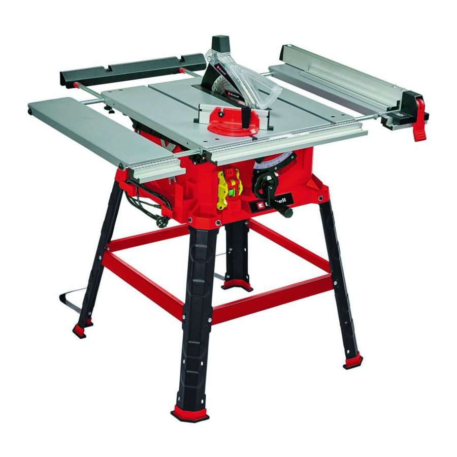
Layout and items supplied
Layout (Fig. 1-26)


- Saw table
- Saw blade guard
- Push stick
- Blade
- Splitter
- Table insert
- Parallel stop
- Hand wheel
- Locking grip for saw blade angle
- Crank arm
- On/Off switch
- Eccentric lever
- Rubber foot
- Cross stop
- Screw for saw blade
- Extractor adapter on housing
- Countersunk head screw
- Screw for parallel stop
- Fastening screw forsplitter
- Locking screw for cross stop
- Slot in saw table
- Scale (cutting width)
- Stop rail for parallel stop
- Stop rail for cross stop
- Shaft
- Knurled screw for parallel stop
- Slot in stop rail
- Guide rail system
- Leg
- Cross strut
- Locking screw for table width extension
- Locking screw for table length extension
- Table width extension (left)
- Table width extension (right)
- Table length extension
- Cap on saw blade guard
- Additional leg
- Wrench, size 10/13 mm
- Wrench, size 10 mm
- Fastening plate
- Pointer (angular setting)
- Scale (angular setting)
- Knurled screw for cross stop
- Adjustment screw (0°)
- Adjustment screw (45°)
- Hexagon screw
- Washer, large
- Lock bolt
- Washer, small
- Spring washer
- Nut
- Recessed head screw
- Screw for hand wheel/crank
- Screw with washer and spring washer
Items supplied
Please check that the article is complete as specified in the scope of delivery. If parts are missing, please contact our service center or the sales outlet where you made your purchase at the latest within 5 working days after purchasing the product and upon presentation of a valid bill of purchase. Also, refer to the warranty table in the service information at the end of the operating instructions.
- Open the packaging and take out the equipment with care.
- Remove the packaging material and any packaging and/or transportation braces (if available).
- Check to see if all items are supplied. Inspect the equipment and accessories for transport damage.
- If possible, please keep the packaging until the end of the guarantee period.
The equipment and packaging material are not toys. Do not let children play with plastic bags, foils or small parts. There is a danger of swallowing or suffocating!
- • Saw blade guard / splitter
- • Push stick
- • Parallel stop •
- Hand wheel •
- Crank arm
- • Rubber foot (4x) •
- Cross stop
- • Screw for parallel stop (2x) •
- Stop rail for parallel stop
- • Knurled screw (2x) •
- Leg (4x)
- • Cross strut (4x)
- • Locking screw for table width extension (4x)
- • Locking screw for table length extension (2x)
- • Table width extension (left)
- • Table width extension (right) •
- Table length extension •
- Additional leg (2x)
- • Wrench, size 10/13 mm •
- Wrench, size 10 mm •
- Hex screw (8x)
- • Washer, large (8x) •
- Lock bolt (8x)
- • Washer, small (12x) •
- Spring washer (8x) •
- Nut (12x)
- • Recessed head screw (6x)
- • Screw with washer and spring washer (4x)
- • Original operating instructions
- • Safety information
Proper use
The bench-type circular saw is designed for the slitting and cross-cutting (only with the cross stop) of all types of timber commensurate with the machine‘s size. The equipment is not to be used for cutting any type of round wood.
The equipment is to be used only for its prescribed purpose. Any other use is deemed to be a case of misuse. The user / operator and not the manufacturer will be liable for any damage or injuries of any kind caused as a result of this.
Please note that our equipment has not been designed for use in commercial, trade or industrial applications. Our warranty will be voided if the machine is used in commercial, trade or industrial businesses or for equivalent purposes.
The equipment is to be operated only with suitable saw blades (saw blades made of HM or CV) It is prohibited to use any type of HSS saw blade and cutting-off wheel.
To use the equipment properly you must also observe the safety information, the assembly instructions and the operating instructions to be found in this manual. All persons who use and service the equipment have to be acquainted with these operating instructions and must be informed about the equipment‘s potential hazards. It is also imperative to observe the accident prevention regulations in force in your area. The same applies for the general rules of health and safety at work. The manufacturer will not be liable for any changes made to the equipment nor for any damage resulting from such changes. Even when the equipment is used as prescribed it is still impossible to eliminate certain residual risk factors. The following hazards may arise in connection with the machine‘s construction and design:
- • Contact with the saw blade in the uncovered saw zone.
- • Reaching into the running saw blade (cut injuries).
- • Kick-back of workpieces and parts of workpieces.
- • Saw blade fracturing.
- • Catapulting of faulty carbide tips from the saw blade.
- • Damage to hearing if essential ear-muffs are not used.
- • Harmful emissions of wood dust when used in closed rooms.
Technical data
AC motor 220-240V ~ 50Hz
Power P S1 1800 W · S6 25% 2200 W
Idling speed n0 4250 rpm
Carbide saw blade Ø 254 x Ø 30 x 2.4 mm
Number of teeth 48
Table size 580 x 555 mm
Table width extension left/right 580 x 150 mm
Table length extension, width 555 mm
Support surface max. 830 x 1055 mm
Cutting height
max. 80 mm / 90°
55 mm / 45°
Height adjustment infinite 0 - 80 mm
Tilting saw blade infinite 0° - 45°
Cross stop angle infinite -45° - 45°
Extractor connection Ø 36 mm
Weight approx. 26.5 kg
Protection class: II/ ![]()
Thickness of the splitter 2.0 mm
Operating mode S6 25%: Continuous operation with idling (cycle time 10 minutes). To ensure that the motor does not become excessively hot, it may only be operated for 25% of the cycle at the specified rating and must then be allowed to idle for 75% of the cycle.
Noise
The noise emission values were measured in accordance with EN 62841.
Operation
LpA sound pressure level. 93.2 dB(A)
KpA uncertainty 3 dB(A)
LWA sound power level 106.2 dB(A)
KWA uncertainty 3 dB(A)
Wear ear-muffs.
The impact of noise can cause damage to hearing.
The stated noise emission values were measured in accordance with a set of standardized criteria and can be used to compare one power tool with another.
The stated noise emission values can also be used to make an initial assessment of exposure.
The noise emission levels may vary from the level specified during actual use, depending on the way in which the power tool is used, especially the type of workpiece it is used for.
Keep the noise emissions and vibrations to a minimum.
- • Only use appliances which are in perfect working order.
- • Service and clean the appliance regularly.
- • Adapt your working style to suit the appliance.
- • Do not overload the appliance.
- • Have the appliance serviced whenever necessary.
- • Switch the appliance off when it is not in use.
Limit the operating time!
All stages of the operating cycle must be considered (for example, times in which the electric tools are switched o and times in which the tool is switched on but operates without load).
Residual risks
Even if you use this electric power tool in accordance with instructions, certain residual risks cannot be rules out. The following hazards may arise in connection with the equipment’s construction and layout:
- Lung damage if no suitable protective dust mask is used.
- Damage to hearing if no suitable ear protection is used.
Before starting the equipment
Before you connect the equipment to the mains supply make sure that the data on the rating plate are identical to the mains data.
Always pull the power plug before making adjustments to the equipment.
- Unpack the bench-type circular saw and check it for damage which may have occurred in transit.
- The machine has to be set up where it can stand firmly, e.g. on a work bench, or it must be bolted to a strong base.
- All covers and safety devices have to be properly fitted before the machine is switched on.
- It must be possible for the saw blade to run freely.
- When working with wood that has been processed before, watch out for foreign bodies such as nails or screws etc.
- Before you actuate the On/Off switch, make sure that the saw blade is correctly fitted and that the machine's moving parts run smoothly.
Assembly
Pull out the power plug before carrying out any maintenance, resetting or assembly work on the circular saw!
Assembling the base frame
(Fig. 3-4)
Make allowance for the weight of the machine and arrange another person to help you if necessary!
• Turn the bench-type circular over and set the saw down on the floor or on some other work surface. Important! Place suitable material (e.g. packaging material) between the table surface and the surface on which it is stood to prevent any damage to the table surface.

Only fasten all the screw connections between the base frame and machine loosely at first. Wait until you have returned the bench-type circular saw to its working position before tightening the screw connections securely. This is so that you can be sure the base frame is aligned level with the surface on which it is stood.
• Use the hexagon screws (46) and washers (47) to fasten the four legs (29) loosely to the saw.
• Then use the lock bolt (48), washer (49), spring washer (50) and nut (51) to screw the cross-struts loosely to the legs. Make sure that the tongue-and-groove connection between the cross-strut (30) and leg (29) engages properly.
• Plug the rubber feet (13) onto the legs (29).
Assembling the table width extension
(Fig. 5, 6)
• Slot the table width extensions (33, 34) into the openings on the left and right-hand sides of the saw table (1).
• Slot the table length extension (35) into the openings on the back of the saw table (1).
• Then, using two recessed head screws (52) for each, secure the table width extensions (33, 34) and the table length extension (35) as shown in Figs. 5 and 6 to prevent them being pulled completely out.
• Fit two locking screws (31) each to the left and right-hand sides of the saw table (1) so that you can lock the table width extensions (33, 34) in a specific position.
• Fit the two locking screws (32) to the back of the saw table (1) so that you can lock the table length extension (35).
A crosstip screwdriver is not supplied with the product.
Standing the bench-type circular saw upright
(2, 7-9)
- Turn the machine over so that it stands on its legs.
- The bench-type circular saw must be stood on a flat surface.
- Then tighten all loose screw connections. Use both the wrenches (38) and (39) to do this.
- Screw the additional legs (37 to the rear legs (29) so that they point towards the rear of the machine. Us the screws (54), washers (49) and nuts (51) to fasten them.
![]()
Don not fit the additional legs (37) too far away from the surface on which the machine stands; they are intended to provide protection against tipping over.- Remove the screw (53) from the shaft (25).
- Slide the hand wheel (8) and then the crank (10) onto the shaft (25) as shown in Fig. 9.
- Important! The shaft (25) and the crank (10) engage with a positive fit, i.e. the flat surface on the shaft (25) and the flat surface in the hub of the crank (10) must lie on top of each other to enable the crank (10) to be slid on.
- Secure the hand wheel (8) and crank (10) with the screw (53).
Changing the table insert
(Figure 12)
- • To prevent increased likelihood of injury, the table insert should be changed whenever it is worn or damaged.
- • Remove the countersunk head screws (17).
- • Remove the worn table insert (6) by pulling it out through the opening at the back past the splitter (5) and the saw blade (4).
- • Fit the replacement table insert by following the above in reverse.
Fitting / removing the splitter together with the saw blade guard
(Fig. 10 - 13)
- Remove the table insert (6) by undoing the countersunk head screws (17) (see Changing the table insert ). Using the crank (10) set the saw blade (4) to the maximum cutting depth.
- Slacken the fastening screw (19) until the gap between the fastening plate (40) and the support surface opposite is approx. 5 mm.
![]()
sDo not completely undo the fastening plate (40). - Insert the splitter (5) together with the saw blade guard in the gap, push it right down as far as it goes and then secure it with the fastening screw (19). Make sure that the splitter has been fitted straight and not wobbly.
- • The splitter (5) must be positioned in the center along an imaginary line extending behind the saw blade (4), so that it is not possible for the material to get jammed.
- • The gap between the blade (4) and the splitter (5) should be 3 mm to 8 mm. (Fig. 13)
- • Push the table insert (6) through the opening at the back over the saw blade (4) and the splitter (5) and insert it in the saw table (1).
- • Use countersunk head screws (17) to fasten the table insert (6).
- • To dismantle, proceed in reverse order.
Fitting/changing the saw blade
(Fig. 14)
- • Before changing the saw blade: Pull out the power plug!
- • Wear work gloves to prevent injury when changing the saw blade.
- • Using the crank (10) set the saw blade (4) to the maximum cutting depth.
- • Remove the table insert (6) by undoing the countersunk head screw (17) (see Changing the table insert ).
- • Remove the splitter (5) together with the saw blade guard (2) (see Fitting / removing the splitter together
- with the saw blade guard).
- • Undo the screw (15) with a wrench (38) on the screw (15) itself and a second wrench (39) on the motor shaft to apply counterpressure.
- •
![]()
Turn the screw (15) in the direction of rotation of the saw blade. - • Take off the outer flange and pull the old saw blade (4) off the inner flange.
- • Clean the blade flange thoroughly before fitting the new blade.
- • Fit and fasten the new saw blade (4) in reverse order.
![]()
Note the running direction. The cutting angle of the teeth must point in running direction, i.e. forwards (see the arrow on the blade guard).- • Refit and set the splitter (5) and the saw blade guard (2) (see Fitting / removing the splitter together with the saw blade guard.)
- • Check to make sure that all safety devices are properly mounted and in good working condition before you begin working with the saw again.
- •
![]()
Every time that you change the saw blade, check that the saw blade guard (2) opens and closes again in accordance with requirements. Also check that the saw blade (4) spins freely in the saw blade guard (2). - •
![]()
Every time that you change the saw blade (4), check to see that it spins freely in the table insert (6) in both perpendicular and 45° angle settings.
![]()
You should replace the table insert (6) immediately whenever it is worn or damaged (see Changing the table insert ). ![]()
The work to change and align the saw blade (4) must be carried out correctly.
Putting away loose parts
(Fig. 15)
- • When not in use, the parallel stop (7), push stick (3) and the two wrenches (38+39) can be secured as shown in Fig. 15a.
- • The cross stop (14) can be secured as shown in Fig. 15b.
Connection for dust extractor
(Fig. 2, 26)
A connection for a dust extractor is provided on the extractor adapter on the housing (16) and on the saw blade guard (2).
Dust extraction using a wet & dry vac
(Fig. 2):
- • A wet & dry vac is not supplied with the product and is available as an accessory.
- • Connect the wet & dry vac to the extractor adapter on the housing (16).
Dust extraction using a vacuum extraction system and extractor adapter set
(Fig. 26):
- The product is not supplied with an extractor adapter set with suction hose (a) and adapter (b) or a vacuum extraction system, which are available as accessories.
- Using a crosstip screwdriver, undo the screw on the cap (36) on the saw blade guard (2). The the cap (36) from the saw blade guard (2).
- Connect the adapter (b) to the extractor adapter on the housing (16).
- Connect the saw blade guard (2) and the adapter (b) to the suction hose (a).
- A vacuum extraction system can now be connected to the 100 mm diameter of the adapter (b).
Using the saw
ON/OFF switch
(Fig. 1, 16 / Item 11)
- • The On/Off switch is covered by an additional cap. This has to be opened to switch on the saw.
- • To turn the saw on, press the green button „I“. Wait for the blade to reach its maximum speed of rotation before commencing with the cut.
- • To turn the equipment off again, press the red button „0“.
Cutting depth
(Fig. 1, 16)
Turn the crank (10) to set the blade (4) to the required cutting depth.
Turn anti-clockwise: smaller cutting depth
Turn clockwise: larger cutting depth
Parallel stop
The parallel stop (7) has to be used when making longitudinal cuts in wooden workpieces.
Stop height
(Fig. 18, 19)
- • The parallel stop (7) which is supplied with the product must be used together with the stop rail (23) when performing longitudinal cuts on thin materials (Fig. 19a).
- • To fasten the stop rail (23) to the parallel stop (7) you have to slacken the two knurled screws (26). Then thread the stop rail (23) with the slot (27) onto the screws (18) and secure it with the knurled screws (26).
- • The parallel stop (7) has to be used without the stop rail (23) when making longitudinal cuts in thicker wooden workpieces (Fig. 19b). To do this, the screws (18) and the knurled screws (26) must also be removed.
- •
![]()
When in use, the stop rail (23) must always be screwed to the side of the parallel stop (7) which faces the saw blade.
Cutting width
(Fig. 17)
- • The parallel stop (7) can be mounted on either side of the saw table (1).
- • The parallel stop (7) has to be mounted in the guide rail (28) of the saw table (1).
- The parallel stop (7) can be set to the required dimension with the help of the scale (22) on the guide rail (28).
- • You can clamp the parallel stop in the required position by pressing the eccentric lever (12)
Setting the stop length
(Fig. 17, 18)
- The stop rail (23) can be moved in longitudinal direction in order to prevent the workpiece from becoming jammed.
- Rule of thumb: The rear end of the stop comes up against an imaginary line that begins roughly at the center of the blade and runs at an angle of 45° to the rear.
- Set the required cutting width
- Slacken the knurled screws (26) and push the stop rail (23) forward until it touches the imaginary 45° line.
- Retighten the knurled screws (26).
The gap between the saw table (1) and the underside of the stop rail (23) must not be too large in order to prevent the material getting jammed. To adjust the distance, the parallel stop (7) must be fastened rst using the eccentric lever (12). Then slacken the knurled screws (26), lower the stop rail (23) down to the saw table (1) and secure the knurled screws (26) again afterwards.
Cross stop
(Fig. 20)
The cross stop (14) has to be used when making cross cuts in wooden workpieces.
- Slide the cross stop (14) into the slot (21) of the saw table.
- Undo the locking screw (20).
- Turn the stop rail (24) until the arrow points to the angle required.
- Re-tighten the fastening screw (20).
- Check the gap between the stop rail (24) and the saw blade (4).
![]()
Do not push the stop rail (24) too far toward the blade. The distance between the stop rail (24) and the blade (4) should be approx. 2 cm.- If necessary, slacken the two knurled screws (43) and adjust the stop rail (24).
- Retighten the knurled screws (43).
Setting the angle of the saw blade
(Fig. 16)
- Undo the locking grip (9).
- To adjust the angle of the saw blade, press the hand wheel (8) towards the machine and turn it at the same time until the pointer (41) is aligned with the desired angular setting on the scale (42).
- Secure the locking grip (9) again.
- If needed, the end stop for adjusting the angle of the saw blade can be readjusted for 0° and 45°. To do this, adjust the two adjustment screws (44) and (45).
Adjusting the table width extensions
(Fig. 8)
- • The table width extensions on the left (33) and right-hand sides (34) on the saw table (1) can be extended outwards.
- • The pull-out width is limited by the recessed head screws (52) (see Technical data)
- • To lock the table width extensions (33, 34) in a specific position, you can secure them with the locking screws (31).
- • If the parallel stop is used with the table width extensions extended, make sure that the parallel stop (7) lies against the guide rail system (28) along the complete clamping width.
- •
![]()
If the parallel stop (7) is not secured properly, this may cause a kickback. - •
![]()
Whenever the table width extensions are extended, always make sure that the workpiece lies safely on the saw table and cannot become jammed. - • The table length extension (35) can be extended at the back and is limited by screws (52) (see Technical data)
- • To lock the table length extension (35) in a specific position, you can secure it with the locking screws (32).
Operation
- After every new adjustment we recommend you to make a trial cut in order to check the new settings.
- After switching on the saw, wait for the blade to reach its maximum speed of rotation before commencing with the cut.
- Take extra care when starting the cut!
- Never use the equipment without the suction function.
- Regularly check and clean the suction channels.
Making longitudinal cuts
(Figure 21)
Longitudinal cutting (also known as slitting) is when you use the saw to cut along the grain of the wood. Press one edge of the workpiece against the parallel stop (7) while the at side lies on the saw table (1). The guard hood (2) must always be lowered over the workpiece. When you make a longitudinal cut, never adopt a working position that is in line with the cutting direction.
- Set the parallel stop (7) in accordance with the workpiece height and the desired width. (See Parallel stop)
- Switch on the saw.
- Place your hands (with fingers closed) flat on the workpiece and push the workpiece along the parallel stop (7) and into the blade (4).
- Guide at the side with your left or right hand (depending on the position of the parallel stop) only as far as the front edge of the guard hood.
- Always push the workpiece through to the end of the splitter (5).
- The offcut piece remains on the saw table (1) until the blade (4) is back in its position of rest.
- Secure long workpieces against falling off at the end of the cut (e.g. with a roller stand etc.).
Cutting narrow workpieces
(Fig. 22)
Be sure to use a push stick (3) when making longitudinal cuts in workpieces smaller than 150 mm in width. A push block is supplied with the saw! Replace a worn or damaged push stick immediately.
Cutting extremely narrow workpieces
(Fig. 23)
- Be sure to use a push block when making longitudinal cuts in very narrow workpieces with a width of 50 mm and less.
- The low guide face of the parallel stop is best used in this case.
- There is no push block supplied with the saw! (Available from your specialist dealer). Replace the push block without delay when it becomes worn.
Making bevel cuts
(Fig. 24)
Bevel cuts must always be used using the parallel stop (7).
If you tilt the saw blade (4) to the left when making angular cuts, position the parallel stop (7) on the right-hand side of the saw blade (4). Guide the workpiece between the saw blade (4) and the parallel stop (7).
- • Set the blade (4) to the desired angle. (See Setting the angle of the saw blade.)
- • Set the parallel stop (7) in accordance with the workpiece width and height (see Parallel stop)
- • Carry out the cut in accordance with the workpiece width (see Cutting narrow workpieces , Cutting extremely narrow workpieces.)
Making cross cuts
(Fig. 25)
- Slide the cross stop (21) into one of the grooves (21) in the table and adjust to the required angle. (See Cross stop) If you also want to tilt the blade (4), use the groove (21) which prevents your hand and the cross stop from making contact with the blade guard.
- Press the workpiece firmly against the cross stop (14).
- Switch on the saw.
- Push the cross stop (14) and the workpiece toward the blade in order to make the cut.
![]()
Always hold the guided part of the workpiece. Never hold the part which is to be cut off.- Push the cross stop (14) forward until the workpiece is cut all the way through.
- Switch off the saw again. Do not remove the offcut until the blade has stopped rotating.
Replacing the power cable
If the power cable for this equipment is damaged, it must be replaced by the manufacturer or its after-sales service or similarly trained personnel to avoid danger.
Cleaning, maintenance and ordering of spare parts
Always pull out the mains power plug before starting any cleaning work.
Cleaning
- • Keep all safety devices, air vents and the motor housing free of dirt and dust as far as possible. Wipe the equipment with a clean cloth or blow it with compressed air at low pressure.
- • We recommend that you clean the device immediately each time you have finished using it.
- • Clean the equipment regularly with a moist cloth and some soft soap. Do not use cleaning agents or solvents; these could attack the plastic parts of the equipment. Ensure that no water can seep into the device. The ingress of water into an electric tool increases the risk of an electric shock.
Carbon brushes
In case of excessive sparking, have the carbon brushes checked only by a qualified electrician.
The carbon brushes should not be rep laced by anyone but a qualified electrician.
Maintenance
There are no parts inside the equipment which require additional maintenance.
Ordering spare parts and accessories
Please provide the following information when ordering spare parts: •
- Type of unit
- • Article number of the unit
- • ID number of the unit
- • Spare part number of the required spare part
For our latest prices and information please go to www.isc-gmbh.info
Tip! For good results we recommend high-quality accessories from ![]() ! www.kwb.eu welcome@kwb.eu
! www.kwb.eu welcome@kwb.eu

Transport
Only ever transport the machine by lifting it by the saw table. Never use the safety devices such as the saw blade guard and stop rails for handling or transporting purposes.
Storage
Store the equipment and accessories in a dark and dry place at above freezing temperature. The ideal storage temperature is between 5 and 30°C. Store the electric tool in its original packaging.
Service information
We have competent service partners in all countries named on the guarantee certificate whose contact details can also be found on the guarantee certificate. These partners will help you with all service requests such as repairs, spare and wearing part orders or the purchase of consumables.
Please note that the following parts of this product are subject to normal or natural wear and that the following parts are therefore also required for use as consumables.
| Category | Example |
| Wear parts* | V-belt, carbon brushes, table insert, push stick |
| Consumables* | Saw blade |
| Missing parts |
* Not necessarily included in the scope of delivery!
![]() In the effect of defects or faults, please register the problem on the internet at www.isc-gmbh.info. Please ensure that you provide a precise description of the problem and answer the following questions in all cases:
In the effect of defects or faults, please register the problem on the internet at www.isc-gmbh.info. Please ensure that you provide a precise description of the problem and answer the following questions in all cases:
- • Did the equipment work at all or was it defective from the beginning?
- • Did you notice anything (symptom or defect) prior to the failure?
- • What malfunction does the equipment have in your opinion (main symptom)?
Describe this malfunction.
To make a claim under the guarantee, please register the defective device at: www.isc-gmbh.info.
Documents / Resources
References
Download manual
Here you can download full pdf version of manual, it may contain additional safety instructions, warranty information, FCC rules, etc.
Advertisement


Need help?
Do you have a question about the TC-TS 2225 U and is the answer not in the manual?
Questions and answers