EINHELL TC-SB 200 + (43.080.13) - Band Saw Manual
- Original operating instructions (124 pages) ,
- Operating instructions manual (273 pages)
Advertisement
- 1 Explanation of the symbols used
- 2 Safety regulations
- 3 Layout and items supplied
- 4 Proper use
- 5 Technical data
-
6
Before using for the first time
- 6.1 Assembly
- 6.2 Tensioning the bandsaw blade
- 6.3 Adjusting the bandsaw blade
- 6.4 Adjusting the support bearing
- 6.5 Adjusting the upper blade guide
- 6.6 Adjusting the saw table to 90°
- 6.7 Blade selection
- 6.8 Replacing the blade
- 6.9 Changing the table insert
- 6.10 Extractor socket
- 6.11 Push stick holder
- 7 Operation
- 8 Transport
- 9 Cleaning, maintenance and ordering of spare parts
- 10 Storage
- 11 Service information
- 12 Documents / Resources
Explanation of the symbols used
(see Fig. 22):

- Danger! - Read the operating instructions to reduce the risk of injury.
- Caution! Wear ear-muffs. The impact of noise can cause damage to hearing.
- Caution! Wear a breathing mask. Dust which is injurious to health can be generated when working on wood and other materials. Never use the device to work on any materials containing asbestos!
- Caution! Wear safety goggles. Sparks generated during working or splinters, chips and dust emitted by the device can cause loss of sight.
- Caution! Risk of injury! Do not reach into the running blade.
- Blade cutting direction
- Conditions of the mains connection
- Power rating
- Speed
- Weight
Safety regulations

When using the equipment, a few safety precautions must be observed to avoid injuries and damage. Please read the complete operating instructions and safety regulations with due care. Keep this manual in a safe place, so that the information is available at all times. If you give the equipment to any other person, hand over these operating instructions and safety regulations as well. We cannot accept any liability for damage or accidents which arise due to a failure to follow these instructions and the safety instructions.
The corresponding safety information can be found in the enclosed booklet.

Read all safety warnings, instructions, illustrations and specifications provided with this power tool. Failure to follow all instructions listed below may result in electric shock, fire and/or serious injury.
Save all warnings and instructions for future reference.
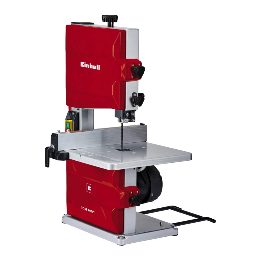
Layout and items supplied
Layout
(Fig. 1-21)

- On/Off switch
- 2.5 mm hex key
- Rubber tire
- Rubber foot
- Pedestal
- Extractor socket
- Lower blade pulley
- Upper blade pulley
- Tensioning screw
- Push-in cover
- Upper blade guide
- Side cover
- Fastening handle
- Saw table mount
- Saw table
- Angle scale
- Table insert
- Wing handle for saw table
- Washer, large
- Quick-lock lever
- Eccentric lever for parallel stop
- Web plate
- Scale for parallel stop
- Parallel stop
- Machine frame
- Blade
- Tilt guard
- 4 mm hex key
- Adjustment handle for upper blade pulley
- Wing handle for upper blade pulley
- Adjustment wheel for blade guide
- Locking handle for blade guide
- Stop screw
- Lock nut
- Push stick
- Push stick holder
- Lateral guide pins, top
- Grub screw for guide pins
- Support bearing, top
- Grub screw for support bearing
- Bearing unit, top
- Grub screw for bearing unit
- Lateral guide pins, bottom
- Grub screw for guide pins
- socket head screw for guide pins
- Support bearing, bottom
- socket head screw for support bearing
- Hexagon screw for rubber foot
- Washer for rubber foot
- Nut for rubber foot
- Recessed head screw for tilt guard
- Washer for tilt guard
- Spring washer for tilt guard
- Countersunk head screw for web plate
- Wing nut for web plate
Items supplied
Please check that the article is complete as specified in the scope of delivery. If parts are missing, please contact our service center or the sales outlet where you made your purchase at the latest within 5 working days after purchasing the product and upon presentation of a valid bill of purchase. Also, refer to the warranty table in the service information at the end of the operating instructions.
- Open the packaging and take out the equipment with care.
- Remove the packaging material and any packaging and/or transportation braces (if available).
- Check to see if all items are supplied.
- Inspect the equipment and accessories for transport damage.
- If possible, please keep the packaging until the end of the guarantee period.
The equipment and packaging material are not toys. Do not let children play with plastic bags, foils or small parts. There is a danger of swallowing or suffocating!
- Bandsaw
- 2.5 mm hex key
- Rubber foot (4x)
- Saw table
- Wing handle for saw table
- Washer, large (2x)
- Quick-lock lever
- Parallel stop
- Tilt guard
- 4 mm hex key
- Push stick
- Hexagon screw for rubber foot (4x)
- Washer for rubber foot (4x)
- Nut for rubber foot (4x)
- Recessed head screw for tilt guard (2x)
- Washer for tilt guard (2x)
- Spring washer for tilt guard (2x)
- Original operating instructions
- Safety instructions
Proper use
This bandsaw is designed for the slitting and cross-cutting of workpieces made of wood or wood-like materials, as well as for cutting plastics and non-ferrous metals.
Magnesium, hard metal and hardened metal are not allowed to be cut on this bandsaw. Round materials are allowed to be cut only with suitable holding devices.
The equipment is to be used only for its prescribed purpose. Any other use is deemed to be a case of misuse. The user / operator and not the manufacturer will be liable for any damage or injuries of any kind caused as a result of this.
Only blades suitable for the machine are allowed to be used. To use the saw properly you must also observe the safety information, the assembly instructions and the operating instructions to be found in this manual.
All persons who operate and service the machine must be acquainted with these instructions and must be informed about potential hazards. It is also imperative to observe the accident prevention regulations in force in your area. The same applies for the general rules of health and safety at work.
The manufacturer will not be liable for any changes made to the machine nor for any damage resulting from such changes.
Even when the machine is used as prescribed it is still impossible to eliminate certain residual risk factors. The following hazards may arise in connection with the machine's construction and design:
- Damage to hearing if essential ear-muffs are not used.
- Harmful emissions of wood dust when used in closed rooms.
- Risk of accident through hand contact with the blade in the uncovered cutting zone.
- Risk of injury when changing the blade (risk of cuts).
- Injuries from catapulted workpieces or parts of workpieces.
- Crushed fingers.
- Injuries from kickback.
- Tilting of the workpiece due to inadequate support.
- Touching the blade.
- Catapulting of pieces of timber and workpieces.
Please note that our equipment has not been designed for use in commercial, trade or industrial applications. Our warranty will be voided if the machine is used in commercial, trade or industrial businesses or for equivalent purposes.
Technical data
Mains voltage: -230 V ~ 50 Hz
Power: S1 250 W · S6 20% 300 W
Idle speed n0: 1400 min-1
Blade: 1405 x 7 x 0.37 mm
Tooth pitch in teeth per 2"Adjusting the support bearing"mm: 6 tpi (teeth per inch)
Blade length min. - max.: 1395-1415 mm
Blade width min. - max.: 6-13 mm
Blade speed V: 900 m/min
Cutting height: 80 mm / 90°; 45 mm / 45°
Reach: 200 mm
Table size: 305 x 305 mm
Tilting range of table: -2° to 45°
Workpiece size: 400 x 400 x 80 mm
Dust extraction connector: Ø 36 mm
Protection class: I
Weight: 1"Angular cuts" kg
Operating mode S6 20%: Continuous operation with idling (cycle time 10 minutes). To ensure that the motor does not become excessively hot it is allowed to be operated for only 20% of the cycle at the specified rating and then must be allowed to idle for 80% of the cycle.
Sound and vibration
Sound and vibration values were measured in accordance with EN 62841.
Operation
LpA sound pressure level: 71 dB(A)
KpA uncertainty: 3 dB(A)
LWA sound power level: 84 dB(A)
KWA uncertainty: 3 dB(A)
Wear ear-muffs.
The impact of noise can cause damage to hearing.
The stated vibration emission levels and stated noise emission values were measured in accordance with a set of standardized criteria and can be used to compare one power tool with another.
The stated vibration emission levels and stated noise emission values can also be used to make an initial assessment of exposure.
The vibration and noise emission levels may vary from the level specified during actual use, depending on the way in which the power tool is used, especially the type of workpiece it is used for.
Keep the noise emissions and vibrations to a minimum.
- Only use appliances which are in perfect working order.
- Service and clean the appliance regularly.
- Adapt your working style to suit the appliance.
- Do not overload the appliance.
- Have the appliance serviced whenever necessary.
- Switch the appliance off when it is not in use.
Limit the operating time!
All stages of the operating cycle must be considered (for example, times in which the electric tools are switched off and times in which the tool is switched on but operates without load).

Residual risks
Even if you use this electric power tool in accordance with instructions, certain residual risks cannot be rules out. The following hazards may arise in connection with the equipment's construction and layout:
- Lung damage if no suitable protective dust mask is used.
- Damage to hearing if no suitable ear protection is used.
Before using for the first time
Make sure the machine stands securely, i.e. bolt it to a workbench or solid base.
- The saw table must be correctly fitted.
- All covers and safety devices must be properly fitted before the machine is switched on.
- It must be possible for the blade to run freely.
- When working with wood that has been previously processed, watch out for foreign bodies such as nails or screws, etc.
- Before you actuate the On/Off switch, make sure that the saw blade is correctly fitted and that the machine's moving parts run smoothly.
- Check that the voltage on the rating plate is the same as your supply voltage before you connect the machine to the power supply.
Pull out the power plug before doing any maintenance or assembly work on the equipment.
Wear safety gloves when contact with the blade (26) is likely.
Assembly
(Fig. 1-4)
Make allowance for the weight of the machine during the assembly work and arrange for another person to help!
- Fit the 4 rubber feet (4) to the corners of the pedestal (5).
- Use the hexagon screws (48), washers (49) and nuts (50) to fasten the rubber feet (4) (see Fig. 2).

- Push the tilt guard (27) into the recesses on the rear of the pedestal (5) and secure it using the recessed head screws (51), washers (52) and spring washers (53) (See Fig. 3).


Fitting the saw table (Fig. 4)


- Remove the web plate (22) by undoing the wing nuts (55) and holding the countersunk head screws (54) steady with the hex key (28).
- Guide the saw table (15) from the rear of the machine with the recess past the blade (26) onto the saw table mount (14).
- Use the wing handle (18) and the washer (19) to secure the saw table (15) on the saw table mount (14).
- Use the quick-lock lever (20) and the washer (19) to secure the saw table (15) on the saw table mount (14).
- Refit the web plate (22) on the saw table (15).
- To dismantle, proceed in reverse order.
Tensioning the bandsaw blade
(Fig. 1/5)

![]()
You must remove the tension from the blade when the bandsaw is not going to be used for some time. It is important therefore to check the blade tension before you switch on the saw.- To be able to check the blade tension, open the two side covers (12) by slackening the fastening handles (13).
- The correct blade tension can be tested by applying pressure to the side of the blade with your finger, somewhere in the middle between the two blade pulleys (7, 8). You should be able to bend the blade (26) only very slightly (approx. 1-2 mm).
- When the blade is tensioned enough, it will produce a metallic sound when tapped.
- Turn the tightening screw (9) clockwise to tension the blade (26).
- After you have adjusted the blade tension, check the blade's running position on the two blade pulleys (7, 8). Adjust the blade if necessary (see "Adjusting the bandsaw blade").
- Close the two side covers (12). Push the side cover against the machine frame (25) as far as it will go. The side cover must latch home with an audible click. Screw the fastening handle (13) tight with the side cover (12) held in pressed position.
![]()
Slacken the blade when you do not want to use it for some time; this will prevent it from overstretching. Turn the tightening screw (9) approx. 3 turns counter-clockwise in order to slacken the blade (26).![]()
The blade might break if the tension is too high.![]()
If the tension is too low, the powered blade pulley (7) will simply spin without the blade moving.
Adjusting the bandsaw blade
(Fig. 1/6)

![]()
Before the blade can be adjusted, it must be properly tensioned (see "Tensioning the bandsaw blade").- Open the two side covers (12) by slackening the fastening handles (13).
- Turn the upper blade pulley (8) slowly by hand in clockwise direction until the blade (26) has settled in a certain position.
- When tensioned, the blade (26) should rest on the rubber tire (3) such that it cannot slip off the rubber tire.
- Please note as a general rule: The rubber tire (3) has an outwardly curved shape, i.e. it is highest at the middle and becomes lower to the front and to the back. The blade should always be guided on the saw plate and not on the teeth. The setting of the teeth is not allowed to be damaged!
- For narrow blades we recommend positioning the blade (26) centrally on the rubber tire. The narrower the blade, the smaller the teeth, which in turn means that the teeth setting is also smaller and more sensitive.
- For wide blades with large teeth we recommend: The blade (26) should rest on the rubber tire (3) without the blade's teeth touching the tire! The teeth of the blade (26) should project beyond the rubber tire (3). If not, the tilt angle of the upper blade pulley (8) must be corrected.
- Slacken the wing handle (30) in order to be able to turn the adjustment handle (29).
- If the blade (26) runs more towards the rear of the blade pulley (8), i.e. towards the machine frame (25), the adjustment handle (29) must be turned counter-clockwise. Then turn the blade pulley (7) slowly with the other hand to check the position of the blade (26).
- If the blade (26) runs towards the front of the blade pulley (8), the adjustment handle (29) must be turned clockwise.
- Secure your adjustment on the upper blade pulley (8) by tightening the wing handle (30).
- Close the two side covers (12). Push the side cover against the machine frame (25) as far as it will go. The side cover must latch home with an audible click. Screw the fastening handle (13) tight with the side cover (12) held in pressed position.
Adjusting the support bearing
(Fig. 7-10)


- Each time after changing the blade you must readjust the support bearings and the lateral guide pins at the lower and upper blade guide.
![]()
Before adjusting the support bearings you must adjust the blade tension as in "Tensioning the bandsaw blade" and the position of the blade (26) on the pulleys as in "Adjusting the bandsaw blade".![]()
The support bearings the lateral guide pins support the blade (26) only during the cutting operation. The blade should not touch the support bearings/guide pins in idling mode.- To open the grub screws described below you can use the 2.5 mm hex key (2), to open the socket head screws you can use the 4 mm hex key (28).
Adjusting the upper support bearings
(Fig. 7/8)
- Adjust the upper blade guide (11) to medium height (see "Adjusting the upper blade guide").
- Slacken the grub screw nut (40) in order to release the support bearing (39).
- Begin by adjusting the position of the lateral guide pins (37) relative to the blade (26). To do so, slacken the grub screw (42) in order to be able to move the upper bearing unit (41). The guide pins (37) should be approx. 1 mm behind the gullet of the blade (26).
![]()
The blade will be rendered useless if the teeth touch the guide pins while the blade is running!- Fasten the position of the bearing unit (41) again with the grub screw (42).
- Now adjust the distance between the support bearing (39) and the rear of the blade (26). Push the support bearing (39) forward until it just fails to touch the blade (leave a gap of approx. 0.5 mm).
- Fasten the position of the support bearing (39) again with the grub screw (40).
- Finally, adjust the distance of the two lateral guide pins (37) from the blade (26). To do so, slacken the grub screws (38) and push the guide pins (37) toward the blade (26) until they just fail to touch the blade (leave a gap of approx. 0.5 mm).
- Fasten the position of the guide pins (37) with the grub screws (38).
Adjusting the lower support bearings
(Fig. 9/10)
- Disassemble the saw table (15). (See "Assembly".)
- Open the lower side cover (12) by slackening the fastening handle (13).
- Begin by adjusting the position of the lateral guide pins (43) relative to the blade (26). To do so, slacken the socket head screw (45) in order to be able to move the lateral guide pins (43). The guide pins (43) should be approx. 1 mm behind the gullet of the blade (26).
![]()
The blade will be rendered useless if the teeth touch the guide pins while the blade is running!- Fasten the position again with the socket head screw (45).
- Now adjust the distance between the support bearing (46) and the rear of the blade (26). Slacken the socket head screw (47) and push the support bearing (46) forward until it just fails to touch the blade (leave a gap of approx. 0.5 mm).
- Fasten the position of the support bearing (46) again with the socket head screw (47).
- Finally, adjust the distance of the two lateral guide pins (43) from the blade (26). To do so, slacken the grub screws (44) and push the guide pins (43) toward the blade (26) until they just fail to touch the blade (leave a gap of approx. 0.5 mm).
- Fasten the position of the guide pins (43) with the grub screws (44).
- Close the side cover (12) again.

After you have adjusted the upper and lower support bearings:
- Turn the blade pulley several turns by hand.
- Check the adjustment of the support bearings and make corrections as required.
Adjusting the upper blade guide
(Fig. 11)

- Undo the locking handle (32).
- Turn the adjustment wheel (31) to lower the blade guide (11) as close as possible to the workpiece to be cut (approx. 2-3 mm gap).
- Re-tighten the locking handle (32).
- Check the adjustment before each cut and make corrections as required.
Adjusting the saw table to 90°
(Fig. 4/12)

- Adjust the blade guide (11) to maximum height (see "Adjusting the upper blade guide").
- Use a 90° set-square (a) to check the angle between the blade (26) and the saw table (15). (This product does not come with a setsquare (a)).
- You can readjust the stop of the saw table (15) if required.
- Slacken the wing handle (18) and the quicklock lever (20) and tilt the saw table (15) to 45°.

- Slacken the lock nut (34).
- Adapt the height of the stop screw (33) by turning it in or out, lower the saw table (15) again onto the stop screw (33) and check again the angle between the blade (26) and the saw table (15).
- Repeat these steps until the angle between the blade (26) and the saw table (15) equals exactly 90°.
- Tighten the lock nut (34) again in order to secure this setting.
- Use the wing handle (18) and the quick-lock lever (20) to secure the saw table again.

Blade selection
The blade supplied with the bandsaw is designed for cutting wood and wood-type materials. When you select a blade you should consider the following criteria:
- With a narrow blade you can cut tighter radii than with a wide blade.
- Wide blades are used to perform straight cuts. This is particularly important when cutting wood because the blade has a tendency to follow the grain of the wood and therefore to deviate easily from the cutting line.
- Finely toothed blades provide smoother cuts but are slower than coarse blades.
Never use warped or lacerated blades!
Replacing the blade
(Figure 1/13/14)
- Before you change the blade: Pull out the power plug!
- To prevent injury: wear gloves when changing the blade!
- Open the two side covers (12) by slackening the fastening handles (13).
- Remove the web plate (22) (see "Assembly").
- Pull the push-in cover (10) up and out.

- Move the blade guide (11) into a position half way between the saw table (15) and the machine frame (25).
- Turn the tightening screw (9) counterclockwise to remove the tension from the blade (26).

- Remove the blade (26) from the blade pulleys (7, 8) and take it out through the slot in the saw table (15).
- Fit the new blade (26) on the two blade pulleys (7, 8).
![]()
Pay attention to the running direction. The cutting angle of the teeth must point in running direction, i.e. downwards from the upper blade guide (11). (See the arrow on the upper side cover (12)).- Re-insert the push-in cover (10).
- Re-fit the web plate (22).
- Tension and adjust the new blade (26), and adjust the upper and lower support bearings (see "Tensioning the bandsaw blade", "Adjusting the bandsaw blade", "Adjusting the support bearing").
- Close the side cover (12).
![]()
Each time after the blade (26) is changed, check that it runs freely in the table insert (17) when set to perpendicular and also when set to 45° (with the saw table (15) tilted).- Check that all safety devices are in good working order before you begin working with the saw again.


Changing the table insert
(Fig. 15)

To prevent a higher risk of injury, the table insert (17) must be replaced whenever it becomes worn or damaged.
- Undo the fastening screw of the table insert (17) with a cross-head screwdriver (b).
(This product does not come with a cross-head screwdriver (b)) - Lift the worn table insert (17) up and out.

- To fit the replacement table insert, proceed in reverse order.

Extractor socket
(Fig. 1c)

The bandsaw is equipped with an extractor socket (6) for extracting sawdust and chips. Connect the bandsaw to a chip extraction system (not included in delivery) by connecting the hose of the extraction system to the extractor socket (6).
Push stick holder
(Fig. 16)
When not in use, the push stick (35) must always be kept in the holder (36).

Operation
On/Off switch
(Fig. 17)

- To turn the saw on, press the green button „I".
- To turn the saw off again, press the red button „0".
![]()
You can switch on the bandsaw only when the upper and lower side covers (12) are fully shut. Both side covers (12) have a safety switch which must latch home with an audible click.
Parallel stop
(Fig. 18)

- The parallel stop (24) can be mounted on the saw table (15) to the left and right of the blade (26).
- Release the eccentric lever (21) and push the parallel stop (24) sideways onto the saw table (15).
- The parallel stop (24) can be set to the required dimension with the help of the scale (23).
- You can clamp the parallel stop (24) in the required position by pressing the eccentric lever (21).
![]()
When you tension the eccentric lever (21) always make sure it is pointing downwards so as not to block the feeding of the workpiece.![]()
You can increase the tension of the parallel stop (24) if required. Proceed as follows: Release the eccentric lever (21), turn it one or more revolutions in clockwise direction in order to increase the tension, then secure the eccentric lever again.- Make sure that the parallel stop (24) is always positioned parallel to the blade (26).
Angular cuts
(Fig. 4)
To enable you to perform angular cuts parallel to the blade (26), the table (15) can be tilted from 0° to 45°.
- Slacken the wing handle (18) and the quicklock lever (20).
- Tilt the saw table (15) until the required angle value is set on the angle scale (16).
- Re-tighten the wing handle (18) and the quick-lock lever (18).
![]()
Always secure the saw table with both handles – the wing handle (18) and the quick-lock lever (20).![]()
With the saw table (15) tilted, place the parallel stop (24) to the right of the blade (26) looking in feeding direction on the side pointing downwards (provided the workpiece is wide enough) in order to stop the workpiece from slipping off.
- After every new adjustment we recommend you to make a trial cut in order to check the new settings.
- For all cutting operations it is important to position the blade guide (11) as close as possible to the workpiece (see "Adjusting the upper blade guide").
- Always guide the workpiece with both hands, holding it flat on the table (15) in order to prevent the blade (26) from jamming.
- Feed the workpiece at a uniform speed that enables the blade to cut through the material without difficulty and without blocking.
- Use the parallel stop (24) on all cuts for which it can be used.
- It is better to make a complete cut in one pass rather than in a stop-and-go operation in which the workpiece might need to be pulled back. If you have to pull back the workpiece nevertheless, switch off the bandsaw first and wait for the blade (26) to stop before pulling the workpiece back.
- The workpiece must always be guided by its longest side during cutting.
When cutting narrow workpieces, it is essential to use a push stick. The push stick (35) must always be kept ready to hand in its holder (36) on the side of the saw.
Making longitudinal cuts
(Fig. 19)

This entails cutting through the workpiece in its longitudinal direction.
- As far as possible, place the parallel stop (24) to the left of the blade (26) for the width required.
- Lower the blade guide (11) onto the workpiece. (See "Adjusting the upper blade guide".)
- Switch on the saw.
- Use your right hand to press one edge of the workpiece against the parallel stop (24) while the flat side rests on the table (15).
- Guide the workpiece along the parallel stop (24) and into the blade (26) at a uniform speed.
![]()
Long workpieces must be secured against falling off at the end of the cutting operation. You can use, for example, a roller stand or similar.
Making angular cuts
(Fig. 20)

- Set the saw table to the desired angle (see "Angular cuts").
- Carry out the cut as described in ("Making longitudinal cuts").
Free-hand cuts
(Fig. 21)

One of the most outstanding features of a bandsaw is the ease with which it allows you to cut curves and radii.
- Lower the blade guide (11) onto the workpiece. (See "Adjusting the upper blade guide".)
- Switch on the saw.
- Hold the workpiece firmly on the saw table (15) and guide it slowly into the blade (26).
- Free-hand cuts should be made at low feed speed so that you can guide the blade (26) along the required line.
- It often pays to first cut off surplus areas around the curves and corners up to about 6 mm from the line.
- In the case of curves which are too tight for the installed blade to cut, you will need to make a series of close-lying cuts up to the front of the curved line. The surplus areas will then drop off when you saw the final radius.
Transport
To transport the bandsaw, hold the pedestal (5) with one hand and the machine frame (25) with the other hand.
Never lift or transport the equipment by its safety partitions.
Cleaning, maintenance and ordering of spare parts
Always pull out the mains power plug before starting any cleaning work.
Cleaning
- Keep all safety devices, air vents and the motor housing free of dirt and dust as far as possible. Wipe the equipment with a clean cloth or blow it with compressed air at low pressure.
- We recommend that you clean the device immediately each time you have finished using it.
- Clean the equipment regularly with a moist cloth and some soft soap. Do not use cleaning agents or solvents; these could attack the plastic parts of the equipment. Ensure that no water can seep into the device. The ingress of water into an electric tool increases the risk of an electric shock.
Maintenance
There are no parts inside the equipment which require additional maintenance.
Ordering spare parts and accessories
Please provide the following information when ordering spare parts:
- Type of unit
- Article number of the unit
- ID number of the unit
- Spare part number of the required spare part For our latest prices and information please go to www.Einhell-Service.com
 Tip! For good results we recommend high-quality accessories from
 ![]() !
!
www.kwb.eu
welcome@kwb.eu

Storage
Store the equipment and accessories in a dark and dry place at above freezing temperature. The ideal storage temperature is between 5 and 30°C. Store the electric tool in its original packaging.
Service information
Please note that the following parts of this product are subject to normal or natural wear and that the following parts are therefore also required for use as consumables.
| Category | Example |
| Wear parts* | Guide roller, V-belt |
| Consumables* | Bandsaw blade |
| Missing parts |
* Not necessarily included in the scope of delivery!
In the effect of defects or faults, please register the problem on the internet at www.Einhell-Service.com. Please ensure that you provide a precise description of the problem and answer the following questions in all cases:
- Did the equipment work at all or was it defective from the beginning?
- Did you notice anything (symptom or defect) prior to the failure?
- What malfunction does the equipment have in your opinion (main symptom)?
Describe this malfunction.
Documents / Resources
References
Download manual
Here you can download full pdf version of manual, it may contain additional safety instructions, warranty information, FCC rules, etc.
Advertisement


Need help?
Do you have a question about the TC-SB 200 + and is the answer not in the manual?
Questions and answers