Makita LS0714, LS0714FL, LS0714L Manual
- Instruction manual (144 pages) ,
- Technical information (26 pages) ,
- Parts breakdown (6 pages)
Advertisement
- 1 Symbols
- 2 SPECIFICATIONS
- 3 SAFETY INSTRUCTIONS FOR MITRE SAWS
- 4 INSTALLATION
-
5
FUNCTIONAL DESCRIPTION
- 5.1 Blade guard
- 5.2 Positioning kerf board
- 5.3 Maintaining maximum cutting capacity
- 5.4 Stopper arm
- 5.5 Sub-fence
- 5.6 Adjusting the miter angle
- 5.7 Adjusting the bevel angle
- 5.8 Adjusting the lever position
- 5.9 Switch action
- 5.10 Lighting up the lamps
- 5.11 Laser beam action
- 5.12 Aligning the laser line
- 6 ASSEMBLY
-
7
OPERATION
- 7.1 Press cutting (cutting small workpieces)
- 7.2 Slide (push) cutting (cutting wide workpieces)
- 7.3 Miter cutting
- 7.4 Bevel cut
- 7.5 Compound cutting
- 7.6 Cutting crown and cove moldings
- 7.7 Measuring
- 7.8 In the case of left bevel cut
- 7.9 In the case of right bevel cut
- 7.10 Cutting aluminum extrusion
- 7.11 Wood facing
- 7.12 Cutting repetitive lengths
- 7.13 Groove cutting
- 7.14 Carrying tool
- 8 MAINTENANCE
- 9 OPTIONAL ACCESSORIES
- 10 Documents / Resources
Symbols
The following show the symbols used for the equipment. Be sure that you understand their meaning before use.
![]()
Read instruction manual.

DOUBLE INSULATION

Wear safety glasses.

To avoid injury from flying debris, keep holding the saw head down, after making cuts, until the blade has come to a complete stop.
When performing slide cut, first pull carriage fully and press down handle, then push carriage toward the guide fence.

Do not place hand or fingers close to the blade.

For your safety, remove the chips, small pieces, etc. from the table top before operation.

Always set SUB-FENCE to left position when performing left bevel cuts. Failure to do so may cause serious injury to operator.

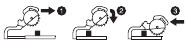
To loosen the bolt, turn it clockwise.

Never look into the laser beam. Direct laser beam may injure your eyes.
SPECIFICATIONS
| Model | LS0714 | LS0714FL | LS0714L |
| Blade diameter | 190 mm | ||
| Hole (arbor) diameter (country specific) | 20 mm or 15.88 mm | ||
| Max. kerf thickness of the saw blade | 2.2 mm | ||
| Max. Miter angle | Left 47°, Right 57° | ||
| Max. Bevel angle | Left 45°, Right 5° | ||
| No load speed (min-1) | 6,400 min-1 | ||
| Laser Type | — | Red Laser 650 nm, < 1mW ( Laser Class 2 ) | |
| Dimensions (L x W x H) | 670 mm x 430 mm x 458 mm | ||
| Net weight | 14.2 kg | 14.8 kg | 14.6 kg |
- Due to our continuing program of research and development, the specifications herein are subject to change withoutnotice.
- Specifications may differ from country to country.
- Weight according to EPTA-Procedure 01/2014
Max. Cutting capacities (H x W) with blade 190 mm in diameter.
| Miter angle | Bevel angle | ||
| 45° (left) | 0° | 5° (right) | |
| 0° | *45 mm x 265 mm Note 1 | *60 mm x 265 mm Note 1 | — |
| 40 mm x 300 mm | 52 mm x 300 mm | 40 mm x 300 mm | |
| 45° (left and right) | *45 mm x 185 mm Note 2 | *60 mm x 185 mm Note 2 | — |
| 40 mm x 212 mm | 52 mm x 212 mm | — | |
| 57° (right) | — | *60 mm x 145 mm Note 3 | — |
| 52 mm x 163 mm | |||
 Note
Note
* mark indicates that a wood facing with the following thickness is used.
1: When using a wood facing 20 mm thick.
2: When using a wood facing 15 mm thick.
3: When using a wood facing 10 mm thick.
Intended use
The tool is intended for accurate straight and miter cutting in wood. With appropriate saw blades, aluminum can also be sawed.
Power supply
The tool should be connected only to a power supply of the same voltage as indicated on the nameplate, and can only be operated on single-phase AC supply. They are double-insulated and can, therefore, also be used from sockets without earth wire.
For public low-voltage distribution systems of between 220 V and 250 V
Switching operations of electric apparatus cause voltage fluctuations. The operation of this device under unfavorable mains conditions can have adverse effects to the operation of other equipment. With a mains impedance equal or less than 0.46 Ohms it can be presumed that there will be no negative effects. The mains socket used for this device must be protected with a fuse or protective circuit breaker having slow tripping characteristics.
General power tool safety warnings

Read all safety warnings, instructions, illustrations and specifications provided with this power tool. Failure to follow all instructions listed below may result in electric shock, fire and/or serious injury.
Save all warnings and instructions for future reference.
The term "power tool" in the warnings refers to your mains-operated (corded) power tool or battery-operated (cordless) power tool.
SAFETY INSTRUCTIONS FOR MITRE SAWS
- Mitre saws are intended to cut wood or wood-like products, they cannot be used with abrasive cutoff wheels for cutting ferrous material such as bars, rods, studs, etc. Abrasive dust causes moving parts such as the lower guard to jam. Sparks from abrasive cutting will burn the lower guard, the kerf insert and other plastic parts.
- Use clamps to support the workpiece whenever possible. If supporting the workpiece by hand, you must always keep your hand at least 100 mm from either side of the saw blade. Do not use this saw to cut pieces that are too small to be securely clamped or held by hand. If your hand is placed too close to the saw blade, there is an increased risk of injury from blade contact.
- The workpiece must be stationary and clamped or held against both the fence and the table. Do not feed the workpiece into the blade or cut "freehand" in any way. Unrestrained or moving workpieces could be thrown at high speeds, causing injury.
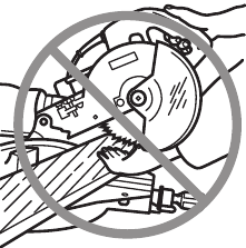
- Push the saw through the workpiece. Do not pull the saw through the workpiece. To make a cut, raise the saw head and pull it out over the workpiece without cutting, start the motor, press the saw head down and push the saw through the workpiece. Cutting on the pull stroke is likely to cause the saw blade to climb on top of the workpiece and violently throw the blade assembly towards the operator.
- Never cross your hand over the intended line of cutting either in front or behind the saw blade. Supporting the workpiece "cross handed" i.e. holding the workpiece to the right of the saw blade with your left hand or vice versa is very dangerous.
![]()
- Do not reach behind the fence with either hand closer than 100 mm from either side of the saw blade, to remove wood scraps, or for any other reason while the blade is spinning. The proximity of the spinning saw blade to your hand may not be obvious and you may be seriously injured.
- Inspect your workpiece before cutting. If the workpiece is bowed or warped, clamp it with the outside bowed face toward the fence. Always make certain that there is no gap between the workpiece, fence and table along the line of the cut. Bent or warped workpieces can twist or shift and may cause binding on the spinning saw blade while cutting. There should be no nails or foreign objects in the workpiece.
- Do not use the saw until the table is clear of all tools, wood scraps, etc., except for the workpiece. Small debris or loose pieces of wood or other objects that contact the revolving blade can be thrown with high speed.
- Cut only one workpiece at a time. Stacked multiple workpieces cannot be adequately clamped or braced and may bind on the blade or shift during cutting.
- Ensure the mitre saw is mounted or placed on a level, firm work surface before use. A level and firm work surface reduces the risk of the mitre saw becoming unstable.
- Plan your work. Every time you change the bevel or mitre angle setting, make sure the adjustable fence is set correctly to support the workpiece and will not interfere with the blade or the guarding system. Without turning the tool "ON" and with no workpiece on the table, move the saw blade through a complete simulated cut to assure there will be no interference or danger of cutting the fence.
- Provide adequate support such as table extensions, saw horses, etc. for a workpiece that is wider or longer than the table top. Workpieces longer or wider than the mitre saw table can tip if not securely supported. If the cut-off piece or workpiece tips, it can lift the lower guard or be thrown by the spinning blade.
- Do not use another person as a substitute for a table extension or as additional support. Unstable support for the workpiece can cause the blade to bind or the workpiece to shift during the cutting operation pulling you and the helper into the spinning blade.
- The cut-off piece must not be jammed or pressed by any means against the spinning saw blade. If confined, i.e. using length stops, the cut-off piece could get wedged against the blade and thrown violently.
- Always use a clamp or a fixture designed to properly support round material such as rods or tubing. Rods have a tendency to roll while being cut, causing the blade to "bite" and pull the work with your hand into the blade.
- Let the blade reach full speed before contacting the workpiece. This will reduce the risk of the workpiece being thrown.
- If the workpiece or blade becomes jammed, turn the mitre saw off. Wait for all moving parts to stop and disconnect the plug from the power source and/or remove the battery pack. Then work to free the jammed material. Continued sawing with a jammed workpiece could cause loss of control or damage to the mitre saw.
- After finishing the cut, release the switch, hold the saw head down and wait for the blade to stop before removing the cut-off piece. Reaching with your hand near the coasting blade is dangerous.
- Hold the handle firmly when making an incomplete cut or when releasing the switch before the saw head is completely in the down position. The braking action of the saw may cause the saw head to be suddenly pulled downward, causing a risk of injury.
- Only use the saw blade with the diameter that is marked on the tool or specified in the manual. Use of an incorrectly sized blade may affect the proper guarding of the blade or guard operation which could result in serious personal injury.
- Only use the saw blades that are marked with a speed equal or higher than the speed marked on the tool.
- Do not use the saw to cut other than wood, aluminum or similar materials.
- (For European countries only) Always use the blade which conforms to EN8471.
Additional instructions
- Make workshop kid proof with padlocks.
- Never stand on the tool. Serious injury could occur if the tool is tipped or if the cutting tool is unintentionally contacted.
- Never leave the tool running unattended. Turn the power off. Do not leave tool until it comes to a complete stop.
- Do not operate saw without guards in place. Check blade guard for proper closing before each use. Do not operate saw if blade guard does not move freely and close instantly. Never clamp or tie the blade guard into the open position.
- Keep hands out of path of saw blade. Avoid contact with any coasting blade. It can still cause severe injury.
- To reduce the risk of injury, return carriage to the full rear position after each crosscut operation.
- Always secure all moving portions before carrying the tool.
- Stopper pin which locks the cutter head down is for carrying and storage purposes only and not for any cutting operations.
- Check the blade carefully for cracks or damage before operation. Replace cracked or damaged blade immediately. Gum and wood pitch hardened on blades slows saw and increases potential for kickback. Keep blade clean by first removing it from tool, then cleaning it with gum and pitch remover, hot water or kerosene. Never use gasoline to clean blade.
- While making a slide cut, KICKBACK can occur. KICKBACK occurs when the blade binds in the workpiece during a cutting operation and the saw blade is driven rapidly towards the operator. Loss of control and serious personal injury can result. If blade begins to bind during a cutting operation, do not continue to cut and release switch immediately.
- Use only flanges specified for this tool.
- Be careful not to damage the arbor, flanges(especially the installing surface) or bolt. Damage to these parts could result in blade breakage.
- Make sure that the turn base is properly secured so it will not move during operation. Use the holes in the base to fasten the saw to a stable work platform or bench. NEVER use tool where operator positioning would be awkward.
- Make sure the shaft lock is released before the switch is turned on.
- Be sure that the blade does not contact the turn base in the lowest position.
- Hold the handle firmly. Be aware that the saw moves up or down slightly during start-up and stopping.
- Make sure the blade is not contacting the workpiece before the switch is turned on.
- Before using the tool on an actual workpiece, let it run for a while. Watch for vibration or wobbling that could indicate poor installation or a poorly balanced blade.
- Stop operation immediately if you notice anything abnormal.
- Do not attempt to lock the trigger in the "ON"position.
- Always use accessories recommended in this manual. Use of improper accessories such as abrasive wheels may cause an injury.
- Some material contains chemicals which may be toxic. Take caution to prevent dust inhalation and skin contact. Follow material supplier safety data.
Additional safety rules for the laser
- LASER RADIATION, DO NOT STARE INTO THE BEAM OR VIEW DIRECTLY WITH OPTICAL INSTRUMENTS, CLASS 2M LASER PRODUCT.
SAVE THESE INSTRUCTIONS.
DO NOT let comfort or familiarity with product (gained from repeated use) replace strict adherence to safety rules for the subject product. MISUSE or failure to follow the safety rules stated in this instruction manual may cause serious personal injury.
INSTALLATION
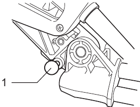
Bench mounting
When the tool is shipped, the handle is locked in the lowered position by the stopper pin. Release the stopper pin by lowering the handle slightly and pulling the stopper pin.
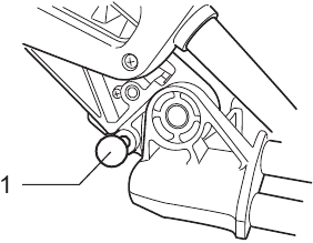
(Fig. 1)
- Stopper pin
This tool should be bolted with two bolts to a level and stable surface using the bolt holes provided in the tool's base. This will help prevent tipping and possible injury.
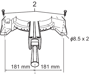
(Fig. 2)
- Bolt
Turn the adjusting bolt clockwise or counterclockwise so that it comes into a contact with the floor surface to keep the tool stable.

(Fig. 3)
- Adjusting bolt
Installing the holders and holder assemblies
(Fig. 4 & 5)
NOTE:
- In some countries, the holders and holder assemblies may not be included in the tool package as standard accessory.
The holders and the holder assemblies support workpieces horizontally. Tighten the fence shafts to the holder assemblies using the hex wrench.
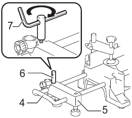
(Fig. 4)
- Holder
- Holder assembly
- Fence shaft
- Hex wrench
Install the holders and the holder assemblies on both side as shown in the figure. When installing, make sure that the fence shaft is in the same line of the guide fence when installed to the tool.

(Fig. 5)
- Screw
Then tighten the screws firmly to secure the holders and the holder assemblies.
FUNCTIONAL DESCRIPTION
- Always be sure that the tool is switched off and unplugged before adjusting or checking function on the tool.
Blade guard
(Fig. 6 & 7)
When lowering the handle, the blade guard rises automatically. The guard is spring loaded so it returns to its original position when the cut is completed and the handle is raised. NEVER DEFEAT OR REMOVE THE BLADE GUARD OR THE SPRING WHICH ATTACHES TO THE GUARD.
In the interest of your personal safety, always maintain the blade guard in good condition. Any irregular operation of the blade guard should be corrected immediately. Check to assure spring loaded return action of guard. NEVER USE THE TOOL IF THE BLADE GUARD OR SPRING ARE DAMAGED, FAULTY OR REMOVED. DOING SO IS HIGHLY DANGEROUS AND CAN CAUSE SERIOUS PERSONAL INJURY.
If the see-through blade guard becomes dirty, or sawdust adheres to it in such a way that the blade is no longer easily visible, unplug the saw and clean the guard carefully with a damp cloth. Do not use solvents or any petroleum-based cleaners on the plastic guard.
(Fig. 6)
- Blade guard
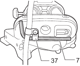
If the blade guard is especially dirty and vision through the guard is impaired, use the supplied hex wrench to loosen the hex socket bolt holding the center cover. Loosen the hex socket bolt by turning it counterclockwise and raise the blade guard and center cover. With the blade guard so positioned, cleaning can be more completely and efficiently accomplished. When cleaning is complete, reverse procedure above and secure bolt. Do not remove spring holding blade guard. If guard becomes discolored through age or UV light exposure, contact a Makita service center for a new guard. DO NOT DEFEAT OR REMOVE GUARD.
(Fig. 7)
Positioning kerf board
(Fig. 8 & 9)
This tool is provided with the kerf boards in the turn base to minimize tearing on the exit side of a cut. The kerf boards are factory adjusted so that the saw blade does not contact the kerf boards. Before use, adjust the kerf boards as follows:
First, unplug the tool. Loosen all the screws (2 each on left and right) securing the kerf boards. Re-tighten them only to the extent that the kerf boards can still be easily moved by hand. Lower the handle fully and push in the stopper pin to lock the handle in the lowered position. Loosen two clamp screws which secure the slide poles. Pull the carriage toward you fully. Adjust the kerf boards so that the kerf boards just contact the sides of the blade teeth. Tighten the front screws (do not tighten firmly). Push the carriage toward the guide fence fully and adjust the kerf boards so that the kerf boards just contact the sides of blade teeth. Tighten the rear screws (do not tighten firmly).
(Fig. 8)
- Thumb screw
- Kerf board
After adjusting the kerf boards, release the stopper pin and raise the handle. Then tighten all the screws securely.

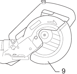
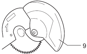
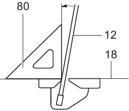
(Fig. 9)
12 Saw blade
13 Blade teeth
14 Left bevel cut
15 Straight cut

- Before and after changing the bevel angle, always adjust the kerf boards as described above.
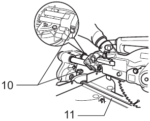
Maintaining maximum cutting capacity
(Fig. 10 & 11)
This tool is factory adjusted to provide the maximum cutting capacity for a 190 mm saw blade. When installing a new blade, always check the lower limit position of the blade and if necessary, adjust it as follows: First, unplug the tool. Push the carriage toward the guide fence fully and lower the handle completely. Use the hex wrench to turn the adjusting bolt until the periphery of the blade extends slightly below the top surface of the turn base at the point where the front face of the guide fence meets the top surface of the turn base.
(Fig. 10)
16 Turn base
17 Guide fence
With the tool unplugged, rotate the blade by hand while holding the handle all the way down to be sure that the blade does not contact any part of the lower base. Readjust slightly, if necessary.

(Fig. 11)
18 Top surface of turn table
19 Periphery of blade
- After installing a new blade, always be sure that the blade does not contact any part of the lower base when the handle is lowered completely. Always do this with the tool unplugged.
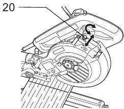
Stopper arm
(Fig. 12)
20 Adjusting screw
21 Stopper arm
The lower limit position of the blade can be easily adjusted with the stopper arm. To adjust it, move the stopper arm in the direction of the arrow as shown in the figure. Adjust the adjusting screw so that the blade stops at the desired position when lowering the handle fully.
Sub-fence

(Fig. 13)
- Sub-fence
Country specific
- When performing left bevel cuts, flip the sub-fence outward. Otherwise, it may contact the blade or a part of the tool, and may result in serious injury to the operator.
This tool is equipped with the sub-fence. Usually position the sub-fence inside. However, when performing left bevel cuts, flip it outward.
Adjusting the miter angle

(Fig. 14)
23 Lock lever
24 Miter scale
25 Pointer
26 Grip
Loosen the grip by turning counterclockwise. Turn the turn base while pressing down the lock lever. When you have moved the grip to the position where the pointer points to the desired angle on the miter scale, securely tighten the grip clockwise.
- When turning the turn base, be sure to raise the handle fully.
- After changing the miter angle, always secure the turn base by tightening the grip firmly.
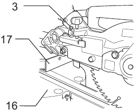
Adjusting the bevel angle
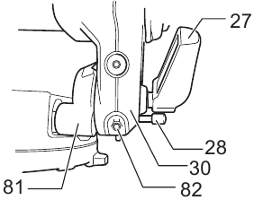
(Fig. 15 & 16)
To adjust the bevel angle, loosen the lever at the rear of the tool counterclockwise.
Push the handle to the left to tilt the saw blade until the pointer points to the desired angle on the bevel scale. Then tighten the lever clockwise firmly to secure the arm. To tilt the blade to the right, push the release button at the rear of the tool while tilting the blade slightly to the left after loosening the lever. With the release button depressed, tilt the saw blade to the right.

Fig. 15 & 16
27 Lever
28 Release button
29 Bevel scale
30 Arm
- When tilting the saw blade, be sure to raise the handle fully.
- After changing the bevel angle, always secure the arm by tightening the lever clockwise.
- When changing bevel angles, be sure to position the kerf boards appropriately as explained in the "Positioning kerf board" section.
Adjusting the lever position

(Fig. 17)
The lever can be re-positioned at every angle 30° when the lever does not provide full tightening. Loosen and remove the screw that secures the lever at the rear of the tool. Remove the lever and install it again so that it is slightly above the level. Secure the lever with the screw firmly.
Switch action

(Fig. 18)
31 Switch trigger
32 Lock-off button
33 Hole for padlock
- Before plugging in the tool, always check to see that the switch trigger actuates properly and returns to the "OFF" position when released. Do not pull the switch trigger hard without pressing in the lock-off button. This can cause switch breakage. Operating a tool with a switch that does not actuate properly can lead to loss of control and serious personal injury.
- NEVER use tool without a fully operative switch trigger. Any tool with an inoperative switch is HIGHLY DANGEROUS and must be repaired before further usage or serious personal injury may occur.
- NEVER defeat the lock-off button by taping down or some other means. A switch with a negated lock off button may result in unintentional operation and serious personal injury.
- NEVER use the tool if it runs when you simply pull the switch trigger without pressing the lock-off button. A switch in need of repair may result in unintentional operation and serious personal injury. Return tool to a Makita service center for proper repairs BEFORE further usage.
To prevent the switch trigger from being accidentally pulled, a lock-off button is provided. To start the tool, press in the lock-off button and pull the switch trigger.
Release the switch trigger to stop.
A hole is provided in the switch trigger for insertion of a padlock to lock the tool off.
- Do not use a lock with a shank or cable any smaller than 6.35 mm in diameter. A smaller shank or cable may not properly lock the tool in the off position and unintentional operation may occur resulting in serious personal injury.
Lighting up the lamps
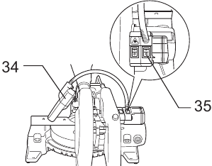
(Fig. 19)
34 Light
35 Light switch
For model LS0714FL
- This is not a rainproof light. Do not wash the light in water or use it in a rain or a wet area. Such a conduct can cause an electric shock and fume.
- Do not touch the lens of the light, as it is very hot while it is lighted or shortly after it is turned off. This may cause a burn to a human body.
- Do not apply impact to the light, which may cause damage or shorted service time to it.
- Do not keep casting the beam of the light to your eyes. This can cause your eyes to be hurt.
- Do not cover the light with clothes, carton, cardboard or similar objects while it is lighted, which can cause a fire or an ignition.
Push the upper position of the switch for turning on the light and the lower position for off.
Move the light to shift an area of lighting.
NOTE:
- Use a dry cloth to wipe the dirt off the lens of lamp. Be careful not to scratch the lens of light, or it may lower the illumination.
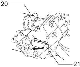
Laser beam action
(Fig. 20 & 21)
For model LS0714FL, LS0714L
- Never look into the laser beam. Direct laser beam may injure your eyes.
- LASER RADIATION, DO NOT STARE INTO THE BEAM OR VIEW DIRECTLY WITH OPTICAL INSTRUMENTS, CLASS 2M LASER PRODUCT.
To turn on the laser beam, press the upper position (I) of the switch. Press the lower position (O) to turn off.
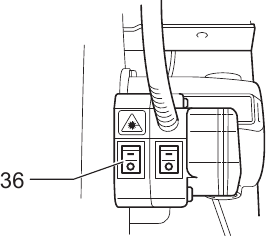
(Fig. 20)
- Switch for laser
Laser line can be shifted to either the left or right side of the saw blade by adjusting the adjusting screw as follows.
- Loosen the adjusting screw by turning it counterclockwise.
- With the adjusting screw loosened, slide the adjusting screw to the right or left as far as it goes.
- Tighten the adjusting screw firmly at the position where it stops sliding.
Laser line is factory adjusted so that it is positioned within 1 mm from the side surface of the blade (cutting position).
(Fig. 21)
NOTE:
- When laser line is dim and almost or entirely invisible because of the direct sunlight in the indoor or outdoor window-by work, relocate the work area to a place not exposed to the direct sunlight.
Aligning the laser line
(Fig. 22)
Laser line can be shifted to either the left or right side of the blade according to the applications of cutting. Refer to explanation titled "Laser beam action" regarding its shifting method.
NOTE:
- Use wood facing against the guide fence when aligning the cutting line with the laser line at the side of guide fence in compound cutting (bevel angle 45 degrees and miter angle right 45 degrees).
- When you obtain correct size on the left side of workpiece
- Shift the laser line to the left of the blade.
- When you obtain correct size on the right side of workpiece
- Shift the laser line to the right of the blade.
- When you obtain correct size on the left side of workpiece
Align the cutting line on your workpiece with the laser line.
ASSEMBLY
- Always be sure that the tool is switched off and unplugged before carrying out any work on the tool.
Hex wrench storage
(Fig. 23)
- Wrench holder
The hex wrench is stored as shown in the figure. When using the hex wrench, pull it out of the wrench holder.
After using the hex wrench, return it to the wrench holder.
Installing or removing saw blade
- Always be sure that the tool is switched off and unplugged before installing or removing the blade.
- Use only the Makita hex wrench provided to install or remove the blade. Failure to do so may result in over-tightening or insufficient tightening of the hex socket bolt. This could cause an injury.
Lock the handle in the raised position by pushing in the stopper pin.
(Fig. 24)
Removing the blade
To remove the blade, use the hex wrench to loosen the hex socket bolt holding the center cover by turning it counterclockwise. Raise the blade guard and center cover.
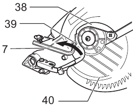
(Fig. 25)
38 Center cover
39 Hex socket bolt
40 Safety cover
Press the shaft lock to lock the spindle and use the hex wrench to loosen the hex socket bolt clockwise. Then remove the hex socket bolt, outer flange and blade.
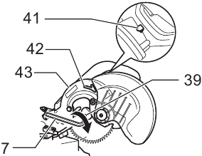
(Fig. 26)
41 Shaft lock
42 Arrow
43 Blade case
Installing the blade
To install the blade, mount it carefully onto the spindle, making sure that the direction of the arrow on the surface of the blade matches the direction of the arrow on the blade case. Install the outer flange and hex socket bolt, and then use the hex wrench to tighten the hex socket bolt (left-handed) securely counterclockwise while pressing the shaft lock.

(Fig. 27 & 28)
44 Outer flange
45 Inner flange
46 Hex socket bolt (left-handed)
47 Spindle
For tool with the inner flange for 15.88 mm hole diameter saw blade
Country specific
Mount the inner flange with its recessed side facing outward onto the mounting shaft and then place circular saw blade (with the ring attached if needed), outer flange and hex bolt.
For tool without the ring

(Fig. 29)
For tool with the ring

(Fig. 30)
- Ring
- If the ring is needed to mount the blade onto the spindle, always be sure that the correct ring for the blade's arbor hole you intend to use is installed between the inner and the outer flanges. Use of the incorrect arbor hole ring may result in the improper mounting of the blade causing blade movement and severe vibration resulting in possible loss of control during operation and in serious personal injury.
For tool with the inner flange for other than 20 mm or 15.88 mm hole diameter saw blade

(Fig. 31)
- Brade mounting part
Country specific
The inner flange has a certain diameter of a blade mounting part on one side of it and a different diameter of blade mounting part on the other side. Choose a correct side on which blade mounting part fits into the saw blade hole perfectly.
- Make sure that the blade mounting part "a" on the inner flange that is positioned outside fits into the saw blade hole "a" perfectly. Mounting the blade on the wrong side can result in the dangerous vibration.
Returning the blade guard
Return the blade guard and center cover to its original position. Then tighten the hex socket bolt clockwise to secure the center cover. Release the handle from the raised position by pulling the stopper pin. Lower the handle to make sure that the blade guard moves properly. Make sure shaft lock has released spindle before making cut.
Connecting a vacuum cleaner

(Fig. 32)
When you wish to perform clean cutting operation, connect a Makita vacuum cleaner.
Dust bag (optional accessory)
")
(Fig. 33)
50 Dust bag
51 Dust nozzle
52 Fastener
The use of the dust bag makes cutting operations clean and dust collection easy. To attach the dust bag, fit it onto the dust nozzle.
When the dust bag is about half full, remove the dust bag from the tool and pull the fastener out. Empty the dust bag of its contents, tapping it lightly so as to remove particles adhering to the insides which might hamper further collection.
Dust box (optional accessory)
(Fig. 34, 35 & 36)
Insert the dust box into the dust nozzle.
Empty the dust box at the earliest possible.
To empty the dust box, open the cover by pushing the button and throw away sawdust.
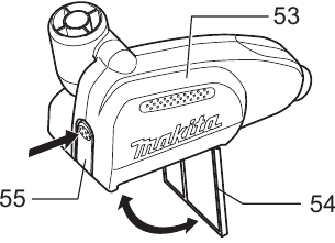
(Fig. 34)
53 Dust box
54 Cover
55 Button
Return the cover to the original position and it locks. Dust box can easily be removed by pulling out while turning it near the dust nozzle on the tool.
")
(Fig. 35 & 36)
56 Cylinder part
57 Sawdust
- Empty the dust box before collected sawdust level reaches the cylinder part.
Securing workpiece

(Fig. 37)
- Support
- It is extremely important to always secure then workpiece properly and tightly with the vise. Failure to do so can cause the tool to be damaged and/or the workpiece to be destroyed. PERSONAL INJURY MAY ALSO RESULT. Also, after a cutting operation, DO NOT raise the blade until the blade has come to a complete stop.
- When cutting long workpieces, use supports that are as high as the top surface level of the turn base. Do not rely solely on the vertical vise and/or horizontal vise to secure the workpiece.
Thin material tends to sag. Support workpiece over its entire length to avoid blade pinch and possible KICKBACK.
Vertical vise
(Fig. 37)
The vertical vise can be installed in two positions on either the left or right side of the guide fence or the holder assembly. Insert the vise rod into the hole in the guide fence or the holder assembly and tighten the screw to secure the vise rod.

(Fig. 38)
59 Vise arm
60 Vise rod
61 Vise knob
Position the vise arm according to the thickness and shape of the workpiece and secure the vise arm by tightening the screw. If the screw to secure the vise arm contacts the guide fence, install the screw on the opposite side of vise arm. Make sure that no part of the tool contacts the vise when lowering the handle fully and pulling or pushing the carriage all the way. If some part contacts the vise, re-position the vise.
Press the workpiece flat against the guide fence and the turn base. Position the workpiece at the desired cutting position and secure it firmly by tightening the vise knob.
- The workpiece must be secured firmly against the turn base and guide fence with the vise during all operations.
Horizontal vise (optional accessory)
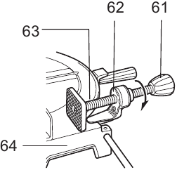
(Fig. 39)
62 Projection
63 Vise shaft
64 Base
The horizontal vise can be installed on the left side of the base. By turning the vise knob counterclockwise, the screw is released and the vise shaft can be moved rapidly in and out. By turning the vise knob clockwise, the screw remains secured. To grip the workpiece, turn the vise knob gently clockwise until the projection reaches its topmost position, then fasten securely. If the vise knob is forced in or pulled out while being turned clockwise, the projection may stop at an angle. In this case, turn the vise knob back counterclockwise until the screw is released, before turning again gently clockwise.
The maximum width of the workpiece which can be secured by the horizontal vise is 120 mm.
- Grip the workpiece only when the projection is at the topmost position. Failure to do so may result in insufficient securing of the workpiece. This could cause the workpiece to be thrown, cause damage to the blade or cause the loss of control, which can result in PERSONAL INJURY.
Holders and holder assembly (optional accessories)
(Fig. 40 & 41)
- For the tool equipped with the holders and the holder assemblies as standard accessories, this type of use is not permitted due to the country regulations.
The holders and the holder assembly can be installed on either side as a convenient means of supporting workpieces horizontally. Install them as shown in the figure. Then tighten the screws firmly to secure the holders and the holder assembly.

(Fig. 40)
When cutting long workpieces, use the holder-rod assembly (optional accessory). It consists of two holder assemblies and two rods 12.

(Fig. 41)
- Rod 12
- Always support long workpieces level with the top surface of the turn base for accurate cuts and to prevent dangerous loss of control of the tool.
OPERATION
- Before use, be sure to release the handle from the lowered position by pulling the stopper pin.
- Make sure the blade is not contacting the workpiece, etc. before the switch is turned on.
- Do not apply excessive pressure on the handle when cutting. Too much force may result in overload of the motor and/or decreased cutting efficiency. Push down handle with only as much force as is necessary for smooth cutting and without significant decrease in blade speed.
- Gently press down the handle to perform the cut. If the handle is pressed down with force or if lateral force is applied, the blade will vibrate and leave a mark (saw mark) in the workpiece and the precision of the cut will be impaired.
- During a slide cut, gently push the carriage toward the guide fence without stopping. If the carriage movement is stopped during the cut, a mark will be left in the workpiece and the precision of the cut will be impaired.
- Do not release the saw head uncontrolled from the fully down position. Uncontrolled saw head may hit you and it will result in personal injury.
Press cutting (cutting small workpieces)
")
(Fig. 42)
- Two clamping screws which secure the slide pole
Workpieces up to 50 mm high and 97 mm wide can be cut in the following way.
Push the carriage toward the guide fence fully and tighten two clamp screws which secure the slide poles clockwise to secure the carriage. Secure the workpiece with the vise. Switch on the tool without the blade making any contact and wait until the blade attains full speed before lowering. Then gently lower the handle to the fully lowered position to cut the workpiece. When the cut is completed, switch off the tool and WAIT UNTIL THE BLADE HAS COME TO A COMPLETE STOP before returning the blade to its fully elevated position.
- Firmly tighten two clamping screws which secure the slide poles clockwise so that the carriage will not move during operation. Insufficient tightening may cause unexpected kickback of the blade. Possible serious PERSONAL INJURY may result.
Slide (push) cutting (cutting wide workpieces)
 cutting (cutting wide workpieces)")
(Fig. 43)
Loosen two clamp screws which secure the slide poles counterclockwise so that the carriage can slide freely. Secure the workpiece with the vise. Pull the carriage toward you fully. Switch on the tool without the blade making any contact and wait until the blade attains full speed. Press down the handle and PUSH THE CARRIAGE TOWARD THE GUIDE FENCE AND THROUGH THE WORKPIECE. When the cut is completed, switch off the tool and WAIT UNTIL THE BLADE HAS COME TO A COMPLETE STOP before returning the blade to its fully elevated position.
- Whenever performing the slide cut, FIRST PULL THE CARRIAGE TOWARD YOU FULLY and press down the handle to the fully lowered position, then PUSH
THE CARRIAGE TOWARD THE GUIDE FENCE. NEVER START THE CUT WITH THE CARRIAGE NOT FULLY PULLED TOWARD YOU. If you perform the slide cut without pulling the carriage fully or if you perform the slide cut toward your direction, the blade may kickback unexpectedly with the potential to cause serious PERSONAL INJURY. - Never perform the slide cut with the handle locked in the lowered position by pressing the stopper pin.
- Never loosen the clamp screw which secures the carriage while the blade is rotating. This may cause serious injury.
Miter cutting
Refer to the previously covered "Adjusting the miter angle".
Bevel cut

(Fig. 44)
Loosen the lever and tilt the saw blade to set the bevel angle (Refer to the previously covered "Adjusting the bevel angle"). Be sure to retighten the lever firmly to secure the selected bevel angle safely. Secure the workpiece with a vise. Make sure the carriage is pulled all the way back toward the operator. Switch on the tool without the blade making any contact and wait until the blade attains full speed. Then gently lower the handle to the fully lowered position while applying pressure in parallel with the blade and PUSH THE CARRIAGE TOWARD THE GUIDE FENCE TO CUT THE WORKPIECE. When the cut is completed, switch off the tool and WAIT UNTIL THE BLADE HAS COME TO A COMPLETE STOP before returning the blade to its fully elevated position.
- Always be sure that the blade will move down to bevel direction during a bevel cut. Keep hands out of path of saw blade.
- During a bevel cut, it may create a condition where by the piece cut off will come to rest against the side of the blade. If the blade is raised while the blade is still rotating, this piece may be caught by the blade, causing fragments to be scattered which is dangerous. The blade should be raised ONLY after the blade has come to a complete stop.
- When pressing the handle down, apply pressure parallel to the blade. If the pressure is not parallel to the blade during a cut, the angle of the blade might be shifted and the precision of the cut will be impaired.
- (Only for European countries) always set the sub-fence outside when performing left bevel cuts.
Compound cutting
Compound cutting is the process in which a bevel angle is made at the same time in which a miter angle is being cut on a workpiece. Compound cutting can be performed at the angle shown in the table.
| Miter angle | Bevel angle |
| Left and Right 45° | Left 0° – 45° |
| Right 50° | Left 0° – 40° |
| Right 55° | Left 0° – 30° |
| Right 57° | Left 0° – 25° |
When performing compound cutting, refer to "Press cutting", "Slide cutting", "Miter cutting" and "Bevel cut" explanations.
Cutting crown and cove moldings
Crown and cove moldings can be cut on a compound miter saw with the moldings laid flat on the turn base. There are two common types of crown moldings and one type of cove moldings; 52/38° wall angle crown molding, 45° wall angle crown molding and 45° wall angle cove molding. See illustrations.

(Fig. 45)
67 52/38° type crown molding
68 45° type crown molding
69 45° type cove molding
There are crown and cove molding joints which are made to fit "Inside" 90° corners ((1) and (2) in Fig. 46 & 47):

(Fig. 46 & 47)
70 Inside corner
71 Outside corner
and "Outside" 90° corners ((3) and (4) in Fig. 46 & 47).
Measuring
Measure the wall length and adjust workpiece on table to cut wall contact edge to desired length. Always make sure that cut workpiece length at the back of the workpiece is the same as wall length. Adjust cut length for angle of cut. Always use several pieces for test cuts to check the saw angles.
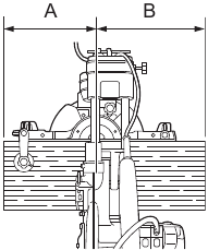
When cutting crown and cove moldings, set the bevel angle and miter angle as indicated in the table (A) and position the moldings on the top surface of the saw base as indicated in the table (B).
In the case of left bevel cut
Table (A)
| Molding position in Fig. 46 & 47 | Bevel angle | Miter angle | |||
| 52/38° type | 45° type | 52/38° type | 45° type | ||
| For inside corner | (1) | Left 33.9° | Left 30° | Right 31.6° | Right 35.3° |
| (2) | Left 31.6° | Left 35.3° | |||
| For outside corner | (3) | ||||
| (4) | Right 31.6° | Right 35.3° | |||
Table (B)
| Molding position in Fig. 46 & 47 | Molding edge against guide fence | Finished piece | |
| For inside corner | (1) | Ceiling contact edge should be against guide fence. | Finished piece will be on the Left side of blade. |
| (2) | Wall contact edge should be against guide fence. | ||
| For outside corner | (3) | Finished piece will be on the Right side of blade. | |
| (4) | Ceiling contact edge should be against guide fence. |
Example:
In the case of cutting 52/38° type crown molding for position (1) in Fig. 46 & 47:
- Tilt and secure bevel angle setting to 33.9° LEFT.
- Adjust and secure miter angle setting to 31.6° RIGHT.
- Lay crown molding with its broad back (hidden) surface down on the turn base with its CEILING CONTACT EDGE against the guide fence on the saw.
- The finished piece to be used will always be on the LEFT side of the blade after the cut has been made.
In the case of right bevel cut
Table (A)
| Molding position in Fig. 46 & 47 | Bevel angle | Miter angle | |||
| 52/38° type | 45° type | 52/38° type | 45° type | ||
| For inside corner | (1) | Right 33.9° | Right 30° | Right 31.6° | Right 35.3° |
| (2) | Left 31.6° | Left 35.3° | |||
| For outside corner | (3) | ||||
| (4) | Right 31.6° | Right 35.3° | |||
Table (B)
| Molding position in Fig. 46 & 47 | Molding edge against guide fence | Finished piece | |
| For inside corner | (1) | Wall contact edge should be against guide fence. | Finished piece will be on the Right side of blade. |
| (2) | Ceiling contact edge should be against guide fence. | ||
| For outside corner | (3) | Finished piece will be on the Left side of blade. | |
| (4) | Wall contact edge should be against guide fence. |
Example:
In the case of cutting 52/38° type crown molding for position (1) in Fig. 46 & 47:
- Tilt and secure bevel angle setting to 33.9° RIGHT.
- Adjust and secure miter angle setting to 31.6° RIGHT.
- Lay crown molding with its broad back (hidden) surface down on the turn base with its WALL CONTACT EDGE against the guide fence on the saw.
- The finished piece to be used will always be on theRIGHT side of the blade after the cut has been made.
Cutting aluminum extrusion
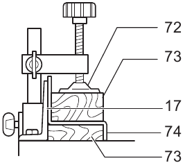
(Fig. 48)
72 Vise
73 Spacer block
74 Aluminum extrusion
When securing aluminum extrusions, use spacer blocks or pieces of scrap as shown in the figure to prevent deformation of the aluminum. Use a cutting lubricant when cutting the aluminum extrusion to prevent build-up of the aluminum material on the blade.
- Never attempt to cut thick or round aluminum extrusions. Thick aluminum extrusions may come loose during operation and round aluminum extrusions cannot be secured firmly with this tool.
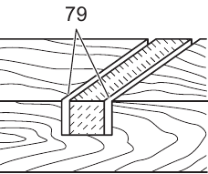
Wood facing

(Fig. 49)
75 Over 15 mm (5/8'')
76 Over 420 mm (16-1/2'')
77 Holes
Use of wood facing helps to assure splinter-free cuts in workpieces. Attach a wood facing to the guide fence using the holes in the guide fence.
See the figure concerning the dimensions for a suggested wood facing.
- Use straight wood of even thickness as the wood facing.
- Use screws to attach the wood facing to the guide fence. The screws should be installed so that the screw heads are below the surface of the wood facing.
- When the wood facing is attached, do not turn the turn base with the handle lowered. The blade and/or the wood facing will be damaged.
Cutting repetitive lengths
(Fig. 50)
- Set plate
- For the tool equipped with the holders and the holder assemblies as standard accessories, this type of use is not permitted due to the country regulations.
When cutting several pieces of stock to the same length, ranging from 220 mm to 385 mm, use of the set plate (optional accessory) will facilitate more efficient operation. Install the set plate on the holder (optional accessory) as shown in the figure.
Align the cutting line on your workpiece with either the left or right side of the groove in the kerf board, and while holding the workpiece from moving, move the set plate flush against the end of the workpiece. Then secure the set plate with the screw. When the set plate is not used, loosen the screw and turn the set plate out of the way.
NOTE:
- Use of the holder-rod assembly (optional accessory)allows cutting repetitive lengths up to 2,200 mm approximately.
Groove cutting
(Fig. 51)
- Cut grooves with blade
A dado type cut can be made by proceeding as follows: Adjust the lower limit position of the blade using the adjusting screw and the stopper arm to limit the cutting depth of the blade. Refer to "Stopper arm" section described on previously.
After adjusting the lower limit position of the blade, cut parallel grooves across the width of the workpiece using a slide (push) cut as shown in the figure. Then remove the workpiece material between the grooves with a chisel. Do not attempt to perform this type of cut using wide (thick) blades or with a dado blade. Possible loss of control and injury may result.
- Be sure to return the stopper arm to the original position when performing other than groove cutting.
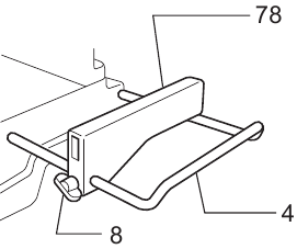
Carrying tool

(Fig. 52 & 53)
Make sure that the tool is unplugged. Secure the blade at 0° bevel angle and the turn base at the full right miter angle position. Secure the slide poles so that the lower slide pole is locked in the position of the carriage fully pulled to operator and the upper poles are locked in the position of the carriage fully pushed forward to the guide fence. Lower the handle fully and lock it in the lowered position by pushing in the stopper pin.
Carry the tool by holding both sides of the tool base as shown in the figure. If you remove the holders, dust bag, etc., you can carry the tool more easily.
- Always secure all moving portions before carrying the tool.
- Stopper pin is for carrying and storage purposes only and not for any cutting operations.
MAINTENANCE
- Always be sure that the tool is switched off and unplugged before attempting to perform inspection or maintenance.
- Never use gasoline, benzine, thinner, alcohol or the like. Discoloration, deformation or cracks may result.
- Always be sure that the blade is sharp and clean for the best and safest performance.
Adjusting the cutting angle
This tool is carefully adjusted and aligned at the factory, but rough handling may have affected the alignment. If your tool is not aligned properly, perform the following:
Miter angle
Push the carriage toward the guide fence and tighten two clamp screws to secure the carriage.
Loosen the grip which secures the turn base. Turn the turn base so that the pointer points to 0° on the miter scale. Then turn the turn base slightly clockwise and counterclockwise to seat the turn base in the 0° miter notch. (Leave as it is if the pointer does not point to 0°.) Loosen the hex socket bolts securing the guide fence using the hex wrench.

(Fig. 54)
Lower the handle fully and lock it in the lowered position by pushing in the stopper pin. Square the side of the blade with the face of the guide fence using a triangular rule, try-square, etc. Then securely tighten the hex socket bolts on the guide fence in the order starting from the right side.

(Fig. 55)
- Triangular rule
Make sure that the pointer points to 0° on the miter scale. If the pointer does not point to 0°, loosen the screw which secures the pointer and adjust the pointer so that it will point to 0°.

(Fig. 56)
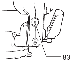
Bevel angle
0° bevel angle
Push the carriage toward the guide fence and tighten two clamp screws to secure the carriage. Lower the handle fully and lock it in the lowered position by pushing in the stopper pin. Loosen the lever at the rear of the tool. Turn the 0° bevel angle adjusting bolt (lower bolt) on the right side of the arm two or three revolutions counterclockwise to tilt the blade to the right.
(Fig. 57)
81 Arm holder
82 0° bevel angle adjusting bolt
Carefully square the side of the blade with the top surface of the turn base using the triangular rule, try square, etc. by turning the 0° bevel angle adjusting bolt clockwise. Then tighten the lever securely.
(Fig. 58)
Make sure that the pointer on the arm point to 0° on the bevel scale on the arm holder. If it does not point to 0°, loosen the screw which secures the pointer and adjust the pointer so that it will point to 0°.

(Fig. 59)
45° bevel angle
Adjust the 45° bevel angle only after performing 0° bevel angle adjustment. To adjust left 45° bevel angle, loosen the lever and tilt the blade to the left fully. Make sure that the pointer on the arm points to 45° on the bevel scale on the arm holder. If the pointer does not point to 45°, turn the 45° bevel angle adjusting bolt (upper bolt) on the right side of the arm until the pointer points to 45°.
(Fig. 60)
- Left 45° bevel angle adjusting bolt
Adjusting the position of laser line

(Fig. 61)
84 Workpiece
85 Cutting line

(Fig. 62)
- Vertical vise
For model LS0714FL, LS0714L
- As the tool is plugged when adjusting the position of laser line, take a full caution especially at switch action. Pulling the switch trigger accidentally cause an accidental start of the tool and personal injury.
- Never look into the laser beam directly. Direct laser beam causes damage to your eyes.
- Never apply a blow or impact to the tool. A blow or impact causes the incorrect position of laser line, damage to the laser beam emitting part or a short life of the tool.
- Have the tool repaired by Makita authorized service center for any failure on the laser unit. No change with different type of laser is permitted.
When adjusting the laser line appears on the left side of the saw blade
 of the saw blade")
- Screw to change the movable range of the adjusting screw
- Adjusting screw
- Hex wrench
- Laser line
- Saw blade
When adjusting the laser line appears on the right side of the saw blade
 of the saw blade")
- Screw to change the movable range of the adjusting screw
- Saw blade
- Laser line
For both adjustments, do as follows.
- Make sure that the tool is unplugged.
- Draw the cutting line on the workpiece and place it on the turn table. At this time, do not secure the workpiece with a vise or similar securing device.
- Lower the blade by lowering the handle and just check to see where the cutting line and the position of the saw blade is. (Decide which position to cut on the line of cut.)
- After decision the position to be cut, return the handle to the original position. Secure the workpiece with the vertical vise without shifting the workpiece from the pre-checked position.
- Plug the tool and turn on the laser switch.
- Adjust the position of laser line as follows.
The position of laser line can be changed as the movable range of the adjusting screw for the laser is changed by turning two screws with a hex wrench. (The movable range of laser line is factory adjusted within 1 mm from the side surface of blade.)
To shift the laser line movable range further away from the side surface of blade, turn the two screws counterclockwise after loosening the adjusting screw. Turn these two screws clockwise to shift it closer to the side surface of the blade after loosening the adjusting screw.
Refer to the section titled "Laser beam action" and adjust the adjusting screw so that the cutting line on your workpiece is aligned with the laser line.
NOTE:
- Check the position of laser line regularly for accuracy.
- Have the tool repaired by Makita authorized service center for any failure on the laser unit.
Replacing fluorescent tube

(Fig. 63)
87 Pull out
88 Push
89 Lamp box
90 Screws
91 Fluorescent tube
For model LS0714FL
- Always be sure that the tool is switched off and unplugged before replacing the fluorescent tube.
- Do not apply force, impact or scratch to a fluorescent tube, which can cause a glass of the fluorescent tube to be broken resulting in a injury to you or your bystanders.
- Leave the fluorescent tube for a while immediately after a use of it and then replace it. If not, you may burn yourself.
Remove screws, which secure Lamp Box for the light. Pull out the Lamp Box keeping pushing lightly the upper position of it as shown in the figure.
Pull out the fluorescent tube and then replace it with Makita original new one.
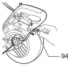
Cleaning of the lens for the laser light
(Fig. 64 & 65)
For model LS0714FL, LS0714L
If the lens for the laser light becomes dirty, or sawdust adheres to it in such a way that the laser line is no longer easily visible, unplug the saw and remove and clean the lens for the laser light carefully with a damp, soft cloth. Do not use solvents or any petroleum-based cleaners on the lens.
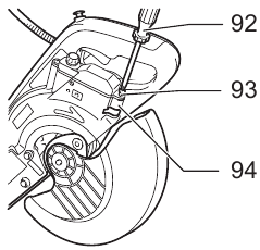
(Fig. 64)
92 Screwdriver
93 Screw (one piece only)
94 Lens for the laser light
To remove the lens for the laser light, remove the saw blade before removing the lens according to the instructions in the section titled "Installing or removing saw blade".
Loosen but do not remove the screw which secures the lens using a screwdriver.
Pull out the lens as shown in the figure.
(Fig. 65)
NOTE:
- If the lens does not come out, loosen the screw further and pull out the lens again without removing the screw.
Replacing carbon brushes

(Fig. 66 & 67)
95 Limit mark
96 Brush holder cap
Remove and check the carbon brushes regularly. Replace when they wear down to the limit mark. Keep the carbon brushes clean and free to slip in the holders. Both carbon brushes should be replaced at the same time. Use only identical carbon brushes.
Use a screwdriver to remove the brush holder caps. Take out the worn carbon brushes, insert the new ones and secure the brush holder caps.
After use
- After use, wipe off chips and dust adhering to the tool with a cloth or the like. Keep the blade guard clean according to the directions in the previously covered section titled "Blade guard". Lubricate the sliding portions with tool oil to prevent rust.
- When storing the tool, pull the carriage toward you fullyso that the slide pole is thoroughly inserted into the turn base.
To maintain product SAFETY and RELIABILITY, repairs, any other maintenance or adjustment should be performed by Makita Authorized Service Centers, always using Makita replacement parts.
OPTIONAL ACCESSORIES
![]() WARNING:
WARNING:
- These Makita accessories or attachments are recommended for use with your Makita tool specified in this manual. The use of any other accessories or attachments may result in serious personal injury.
- Only use the Makita accessory or attachment for its stated purpose. Misuse of an accessory or attachment may result in serious personal injury.
If you need any assistance for more details regarding these accessories, ask your local Makita service center.
- Carbide-tipped saw blades (Refer to our website or contact your local Makita dealer for the correct saw blades to be used for the material to be cut.)
- Vise assembly (Horizontal vise)
- Vertical vise
- Holder set
- Holder assembly
- Holder rod assembly
- Set plate
- Dust bag
- Triangular rule
- Fluorescent tube
- Hex wrench
NOTE:
- Some items in the list may be included in the tool package as standard accessories. They may differ from country to country.
Noise
The typical A-weighted noise level determined according to EN62841-3-9:
Sound pressure level (LpA): 92 dB (A)
Sound power level (LWA): 101 dB (A)
Uncertainty (K): 3 dB (A)
NOTE:
- The declared noise emission value(s) has been measured in accordance with a standard test method and may be used for comparing one tool with another.
- The declared noise emission value(s) may also be used in a preliminary assessment of exposure.
- Wear ear protection
- The noise emission during actual use of the power tool can differ from the declared value(s) depending on the ways in which the tool is used especially what kind of workpiece is processed.
- Be sure to identify safety measures to protect the operator that are based on an estimation of exposure in the actual conditions of use (taking account of all parts of the operating cycle such as the times when the tool is switched off and when it is running idle in addition to the trigger time).
Vibration
The vibration total value (tri-axial vector sum) determined according to EN62841-3-9:
Vibration emission (ah): 2.5 m/s2 or less
Uncertainty (K): 1.5 m/s2
NOTE:
- The declared vibration total value(s) has been measured in accordance with a standard test method and may be used for comparing one tool with another.
- The declared vibration total value(s) may also be used in a preliminary assessment of exposure.
- The vibration emission during actual use of the power tool can differ from the declared value(s) depending on the ways in which the tool is used especially what kind of workpiece is processed.
- Be sure to identify safety measures to protect the operator that are based on an estimation of exposure in the actual conditions of use (taking account of all parts of the operating cycle such as the times when the tool is switched off and when it is running idle in addition to the trigger time).
Documents / ResourcesDownload manual
Here you can download full pdf version of manual, it may contain additional safety instructions, warranty information, FCC rules, etc.
Advertisement


Need help?
Do you have a question about the LS0714 and is the answer not in the manual?
Questions and answers