Table of Contents
Advertisement
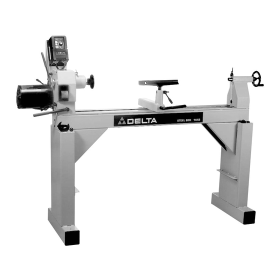
16" Variable Speed
Wood Lathe
(Models 46-745, 46-746, & 46-765X)
PATENT PENDING
PART NO. 434-10-651-0008 - 04-02-03
Copyright © 2003 Delta Machinery
To learn more about DELTA MACHINERY
visit our website at: www.deltamachinery.com.
For Parts, Service, Warranty or other Assistance,
1-800-223-7278 (
1-800-463-3582).
please call
In Canada call
Advertisement
Table of Contents


Need help?
Do you have a question about the 46-745 and is the answer not in the manual?
Questions and answers