Table of Contents
Advertisement
U.S. DESIGN PATENT # D450333111301
U.S. UTILITY PATENT # 6561062B2
To learn more about DELTA MACHINERY
visit our website at: www.deltamachinery.com.
For Parts, Service, Warranty or other Assistance,
1-800-223-7278 (
please call
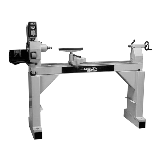
16" Variable Speed
Wood Lathe
(Model 46-756 and 46-755X)
1-800-463-3582).
In Canada call
PART NO.A02990 - 04-08-04
Copyright © 2004 Delta Machinery
Advertisement
Table of Contents

Related Manuals for Delta 46-755X


Summary of Contents for Delta 46-755X
- Page 1 U.S. DESIGN PATENT # D450333111301 U.S. UTILITY PATENT # 6561062B2 To learn more about DELTA MACHINERY visit our website at: www.deltamachinery.com. For Parts, Service, Warranty or other Assistance, 1-800-223-7278 ( please call 16” Variable Speed Wood Lathe (Model 46-756 and 46-755X) Copyright ©...
-
Page 2: Safety Guidelines - Definitions
If you have any questions relative to a particular application, DO NOT use the machine until you have first contacted Delta to deter- mine if it can or should be performed on the product. - Page 3 13. USE RECOMMENDED ACCESSORIES. The use of accessories and attachments not recommended by Delta may cause damage to the machine or injury to the user. 14. USE THE PROPER EXTENSION CORD. Make sure your extension cord is in good condition. When using an extension cord, be sure to use one heavy enough to carry the current your product will draw.
-
Page 4: Additional Safety Rules For Wood Lathes
11. TIGHTEN ALL CLAMP LOCKING HANDLES before operating. 12. ROTATE THE WORKPIECE BY HAND to check clearance before turning the machine “ON”. 13. CLEAR THE LATHE BED OF ALL OBJECTS (tools, scraps of wood, etc.) before turning the machine “ON”. SAVE THESE INSTRUCTIONS. -
Page 5: Power Connections
DO NOT EXPOSE THE MACHINE TO RAIN OR OPERATE THE MACHINE IN DAMP LOCATIONS. Delta Model 46-745 (115 volt) and Delta Models 46-746 and 46-765X (230 volt) operate on 50/60 HZ alternating cur- rent and provide a no-load spindle speed of 0-3200 RPM. Before connecting your tool to the power source, place the switch in the “OFF”... -
Page 6: Extension Cords
3. Grounded, cord-connected machines intended for use on a supply circuit having a nominal rating between 150 - 250 volts, inclusive: If the machine is intended for use on a circuit that has an outlet that looks like the one illustrated in Fig. C, the machine will have a grounding plug that looks like the plug illustrated in Fig. -
Page 7: Functional Description
FUNCTIONAL DESCRIPTION FOREWORD The Delta 46-756 16” adjustable speed wood lathes is a big capacity machine, designed for industry, commercial shops, and schools, or wherever a demand exists for continued accuracy and long life through safe, heavy-duty oper- ation. Carefully unpack the tool and all loose items from the shipping container(s). Remove the protective coating from all unpainted surfaces, especially on the bottom side of the bedways, the clamp plates under the headstock, the tool rest base, and the tailstock. - Page 8 ATTACHING END CAPS Use the supplied hex wrench (B) Fig. 9 to attach the end caps (A) Fig. 8 to both ends of the lathe with button head screws (A) Fig. 9. Insert these through the end cap, then the lathe bed.
- Page 9 ATTACHING LEG INSERTS The lathe is supplied with four leg inserts, one of which is shown (A) Fig. 10. To attach the leg inserts to the pedestals, place one side in the hole provided and gently tap the other side, top, and bottom with a rubber mallet (B) Fig.
-
Page 10: Tailstock Live Center
TOOL REST The tool rest (A) and tool rest base (B) are shown in Fig. 16. To position the tool rest on the lathe bed, lift the clamp handle (C), move the tool rest base and lock it in place by pushing down on the handle (C). To adjust the... -
Page 11: "Off" Position
Although an optional dynamic brake is mentioned in the manual provided with the Baldor Adjustable Speed Controller, Delta does not recommend the use of any optional brake systems on the lathe. Further, DO NOT CHANGE OR ADJUST the con- troller settings that have been pre-set at the factory. - Page 12 To stop the spindle without turning the power off, press the stop button (C) Fig. 22 on the control panel. To restart, press the FWD button (B). The spindle will gradually return to the speed at which it was stopped. 6.
-
Page 13: Operation
The following directions will give the inexperienced operator a beginning point for common lathe operations. Practice on scrap material before attempting serious work. LATHE TOOLS Standard wood turning tools come in several different configurations (Fig. 26). The majority of turnings will require the gouge tool (A) Fig. -
Page 14: Mounting The Work
Place the lubricant on the wood either before or after it is put on the lathe. Many turners use beeswax, tallow, or a wax-and-oil mixture as a lubricant. A ball bearing center is ideal because it eliminates lubricating. -
Page 15: Roughing A Cylinder
ROUGHING A CYLINDER The large gouge is used in the first turning operation by smoothing the sharp corners of the work. Run the lathe at low speed and hold the gouge in the manner shown in Fig. 33 The cut starts about 2 inches from the tailstock end and continues from this point to the end of the tail- stock. -
Page 16: Smoothing A Cylinder
SMOOTHING A CYLINDER To smooth a cylinder, use a large skew chisel. This requires practice, but experience with this tool is very important. Place the cutting point near the center of chisel and high on the work (Fig. 38). Sometimes, in striv- ing for a certain position in relation to the work, the beginner will often overlook this all-important point. - Page 17 Cutting beads quickly and accurately with the small skew is one of the most difficult lathe operations. Various working methods can be used . The first cut is a vertical incision at the point where the two curved sur- faces will eventually come together.
- Page 18 VEE GROOVES Cutting the vee groove demands much the same technique as the bead, except the skew is hinged straight into the work without rotation (Fig. 51). Only one-half of the vee is made at a time, and one, two, or more cuts may be needed on each side to obtain the desired shape.
- Page 19 The gouge is placed on edge on the tool rest so that the grind of the chisel forms an approximate right angle with the work (Figs. 57). The chisel contacts the work at the center of the cutting edge. Hold the tool so that the centerline of the gouge is pointing directly toward the center of the revolving stock.
-
Page 20: Faceplate Turning
1. Remove the tool rest base and the tailstock from the lathe bed. 2. On the headstock, raise the handle (A) Fig. 65 to loosen the tension of the headstock on the lathe bed. 3. Lift the motor slightly and slide the headstock to the end of the lathe bed. -
Page 21: Maintenance
3. While holding the motor (A) Fig. 72 with one hand, use an 11/16” wrench (B) to remove the bolt (C). Lift the motor (A) and remove the belt from the motor pulley. 4. Pull the motor (A) Fig. 72 out, take it to the back of the lathe, and place it on the lathe bed (Fig. 73). Fig. 69 MAINTENANCE Fig. - Page 22 5. Use a Phillips screwdriver (A) Fig. 74 to remove the five cover screws (B) (three of which are shown). The other two screws are located under the power cords. 6. With a 5/16” hex wrench (A) Fig 75, remove the hex screw (B) Fig. 75. NOTE: When re-assembling, pass the screw completely through the pivoting control bracket and into the headstock, allowing the headstock cover to pivot.
-
Page 23: Parts, Service Or Warranty Assistance
Two Year Limited New Product Warranty Delta will repair or replace, at its expense and at its option, any new Delta machine, machine part, or machine accessory which in normal use has proven to be defective in workmanship or material, provided that the customer returns the prod- uct prepaid to a Delta factory service center or authorized service station with proof of purchase of the product within two years and provides Delta with reasonable opportunity to verify the alleged defect by inspection. - Page 24 Phone: (604) 420-0102 Fax: (604) 420-3522 The following are trademarks of PORTER-CABLE • DELTA (Las siguientes son marcas registradas de PORTER-CABLE • DELTA S.A.) (Les marques suivantes sont des marques de fabriquant de la PORTER-CABLE • DELTA): Auto-Set Contractor’s Saw II™, Delta ®...
Need help?
Do you have a question about the 46-755X and is the answer not in the manual?
Questions and answers