Sony XAV-1500 Manual
- Help manual (110 pages) ,
- Operating instructions manual (89 pages) ,
- Manual (45 pages)
Advertisement
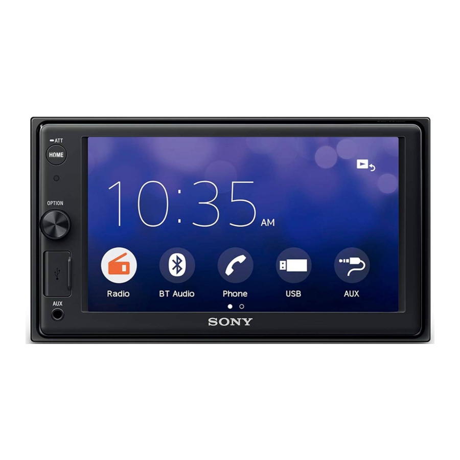
Guide to Parts and Controls
Main Unit

- Display/touch screen
- HOME
Press to display the HOME screen.
![]() ATT (attenuate)
ATT (attenuate)
Press and hold for 1 second to attenuate the sound.
To cancel, press and hold again, or rotate the volume control dial. - Volume control dial
Rotate to adjust the volume when the sound is output.
OPTION
Press to display the OPTION screen. - USB port
- AUX input jack
Screen displays
Playback screen:

HOME screen:

OPTION screen:

- Status indication
![]()
Lights up when the sound is attenuated. ![]()
Lights up when AF (Alternative Frequencies) is available. ![]()
Lights up when the current traffic information (TA: Traffic Announcement) is available. ![]()
Lights up when the Bluetooth® signal is on. Flashes when the connection is in progress. ![]()
Lights up when the audio device is playable by enabling the A2DP (Advanced Audio Distribution Profile). ![]()
Lights up when handsfree calling is available by enabling the HFP (Handsfree Profile). ![]()
Indicates the signal strength status of the connected mobile phone. ![]()
Indicates the remaining battery status of the connected mobile phone. ![]() (source option)
(source option)
Opens the source option menu. The available items differ depending on the source.- Application specific area
Displays playback controls/indications or show the unit's status. Displayed items differ depending on the source. - Clock
Displays the time which are set on the Date/Time setting. ![]() (return to the playback screen)
(return to the playback screen)
Switches from the HOME screen to the playback screen.- Sources and Settings select keys
Changes the source or make various settings. Flick to select the setting icon and other icons. Touch the source icon you want to select.![]() Radio
Radio ![]() BT Audio
BT Audio ![]() Phone
Phone ![]() USB
USB ![]() WebLink
WebLink ![]() AUX
AUX ![]() Rear Camera
Rear Camera ![]() Settings
Settings


 (source option)
 (return to the playback screen)
  Radio
Radio  BT Audio
  Phone
Phone  USB
USB  WebLink
  AUX
AUX  Rear Camera
  Settings
 - Sound select keys
Changes the sound. ![]() (standby)
(standby)
Turns the unit in standby mode (USB charging is still available). To resume, press any buttons.![]() (monitor off)
(monitor off)
Turns off the monitor. When the monitor is turned off, touch any part of the display to turn it back on.![]() (EXTRA BASS)
(EXTRA BASS)
Changes the EXTRA BASS setting.![]() (EQ10/Subwoofer)
(EQ10/Subwoofer)
Changes the EQ10/Subwoofer setting.
 (standby)
 (monitor off)
  (EXTRA BASS)
  (EQ10/Subwoofer)
 Basic Operations
Pairing with a BLUETOOTH Device
When connecting a BLUETOOTH device for the first time, mutual registration (called "pairing") is required. Pairing enables this unit and other devices to recognize each other.

- Press HOME, then touch [Settings]
![]() [Bluetooth]
[Bluetooth] ![]() [Bluetooth Connection]
[Bluetooth Connection] ![]() [ON]
[ON] ![]() [Pairing].
[Pairing].
![]() flashes while the unit is in pairing standby mode.
flashes while the unit is in pairing standby mode. - Perform pairing on the BLUETOOTH device so it detects this unit.
- Select your model name shown on the display of the BLUETOOTH device*.
When pairing is made,![]() stays lit.
stays lit.
* If passkey input is required on the BLUETOOTH device, input [0000].
 [Bluetooth]
 Connecting Rear View Camera
By connecting the optional rear view camera to the CAMERA IN terminal, you can display the picture from the rear view camera. For details, see "Connection/Installation".
To display the picture from the rear view camera
Press HOME, then touch [Rear Camera].
Canceling the Demonstration Mode
- Press HOME, then touch [Settings].
- Touch [General], then touch [Demo] to set to [OFF].
- To exit the setup menu, touch
![]() (back) twice.
(back) twice.
Updating the Firmware
To update the firmware, visit the support site on the back cover, then follow the online instructions.
Note
During the update, do not remove the USB device.
Additional Information
Precautions
- Power antenna (aerial) extends automatically.
- When you transfer ownership or dispose of your car with the unit installed, initialize all the settings to the factory settings by performing the factory reset.
- Do not splash liquid onto the unit.
Notes on safety
- Comply with your local traffic rules, laws, and regulations.
- While driving
- Do not watch or operate the unit, as it may lead to distraction and cause an accident. Park your car in a safe place to watch or operate the unit.
- Do not use the setup feature or any other function which could divert your attention from the road.
- When backing up your car, be sure to look back and watch the surroundings carefully for your safety even if the rear view camera is connected. Do not depend on the rear view camera exclusively.
- While operating
- Do not insert your hands, fingers, or foreign objects into the unit as it may cause injury or damage to the unit.
- Keep small articles out of the reach of children.
- Be sure to fasten seatbelts to avoid injury in the event of sudden movement of the car.
Preventing an accident
Pictures appear only after you park the car and set the parking brake.
If the car starts moving during video playback, the following caution is displayed and you cannot watch the video.
[Video blocked for your safety.]
Do not operate the unit or watch the monitor while driving.
Notes on LCD panel

- Do not get the LCD panel wet or expose it to liquids. This may cause a malfunction.
- Do not press down hard on the LCD panel as doing so can distort the picture or cause a malfunction (i.e., the picture may become unclear or the LCD panel may be damaged).
- Do not touch the panel with objects other than with your finger as it may damage or break the LCD panel.
- Clean the LCD panel with a dry soft cloth. Do not use solvents such as benzine, thinner, commercially available cleaners, or antistatic spray.
- Do not use the unit outside the temperature range 0 ºC to 40 ºC (32 ºF to 104 ºF).
- If your car was parked in a cold or hot place, the picture may not be clear. However, the monitor is not damaged and the picture will become clear after the temperature in your car becomes normal.
- Some stationary blue, red, or green dots may appear on the monitor. These are called "bright spots" and can happen with any LCD. The LCD panel is precision-manufactured with more than 99.99% of its segments functional. However, it is possible that a small percentage (typically 0.01%) of the segments may not light up properly. This will not, however, interfere with your viewing.
Notes on the touch screen
- This unit uses a resistive touch screen. Touch the screen directly with your fingertip.
- Multi-touch operation is not supported on this unit.
- Do not touch the screen with sharp objects such as a needle, pen, or fingernail. Operation with a stylus is not supported on this unit.
- Do not let any objects contact the touch screen. If the screen is touched by an object other than your fingertip, the unit may not respond correctly.
- Since glass material is used for the screen, do not subject the unit to strong shock. If cracking or chipping occurs on the screen, do not touch the damaged part as it may cause injury.
- Keep other electrical devices away from the touch screen. They may cause the touch screen to malfunction.
About iPhone
- Compatible iPhone models: iPhone XS Max, iPhone XS, iPhone XR, iPhone X, iPhone 8 Plus, iPhone 8, iPhone 7 Plus, iPhone 7, iPhone SE, iPhone 6s Plus, iPhone 6s, iPhone 6 Plus, iPhone 6, iPhone 5s
- Use of the Made for Apple badge means that an accessory has been designed to connect specifically to the Apple product(s) identified in the badge, and has been certified by the developer to meet Apple performance standards. Apple is not responsible for the operation of this device or its compliance with safety and regulatory standards. Please note that the use of this accessory with an Apple product may affect wireless performance.
Specifications
Monitor section
Display type: Wide LCD color monitor
Dimensions: 15.7 cm/ 6.2 in System: TFT active matrix Number of pixels:
1,152,000 pixels (800 × 3 (RGB) × 480) Color system:
PAL/NTSC automatic select for CAMERA IN terminal
Radio section
FM
Tuning range: 87.5 MHz – 108.0 MHz
Usable sensitivity: 7 dBf
Signal-to-noise ratio: 70 dB (mono)
Separation at 1 kHz: 45 dB
AM
Tuning range: 531 kHz – 1,602 kHz
Sensitivity: 32 μV
USB player section
Interface: USB port (Hi-speed)
Maximum current: 1.5 A
Wireless communication
Communication System: BLUETOOTH Standard version 3.0 Output:
BLUETOOTH Standard Power Class 2
(Max. Conducted +1 dBm) Maximum communication range*1:
Line of sight approx. 10 m (33 ft) Frequency band:
2.4 GHz band (2.4000 GHz – 2.4835 GHz)
Modulation method: FHSS Compatible BLUETOOTH Profiles*2:
A2DP (Advanced Audio Distribution Profile) 1.3
AVRCP (Audio Video Remote Control Profile) 1.3
HFP (Handsfree Profile) 1.6
PBAP (Phone Book Access Profile) 1.1 Corresponding codec: SBC, AAC
*1 The actual range will vary depending on factors such as obstacles between devices, magnetic fields around a microwave oven, static electricity, reception sensitivity, antenna (aerial) performance, operating system, software application, etc.
*2 BLUETOOTH standard profiles indicate the purpose of BLUETOOTH communication between devices.
Power amplifier section
Outputs: Speaker outputs
Speaker impedance: 4 Ω – 8 Ω
Maximum power output: 55 W × 4 (at 4 Ω)
General
Power requirements: 12 V DC car battery
(negative ground (earth)) Rated current consumption: 10 A
Dimensions:
Approx. 178 mm × 100 mm × 133 mm
(7 1/8 in × 4 in × 5 1/4 in) (w/h/d) Mounting dimensions:
Approx. 182 mm × 111 mm × 120 mm
(7 1/4 in × 4 3/8 in × 4 3/4 in) (w/h/d) Mass: Approx. 0.9 kg (1 lb 16 oz)
Package contents:
Main unit (1)
Parts for installation and connections (1 set) Ask the dealer for detailed information.
Design and specifications are subject to change without notice.
Connection/Installation

- Do not install this unit in a car that has no ACC position. The display of the unit does not turn off even after turning the ignition off, and this causes battery drain.
- Run all ground (earth) leads to a common ground (earth) point.
- Do not get the leads trapped under a screw or caught in moving parts (e.g., seat railing).
- Before making connections, turn the car ignition off to avoid short circuits.
- Connect the power supply leads to the unit and speakers before connecting it to the auxiliary power connector.
- Be sure to insulate any loose unconnected leads with electrical tape for safety.
- Choose the installation location carefully so that the unit will not interfere with normal driving operations.
- Avoid installing the unit in areas subject to dust, dirt, excessive vibration, or high temperature, such as in direct sunlight or near heater ducts.
- Use only the supplied mounting hardware for a safe and secure installation.
Note on the power supply lead (yellow)
When connecting this unit in combination with other stereo components, the amperage rating of the car circuit to which the unit is connected must be higher than the sum of each component's fuse amperage rating.
Note on installing in cars with a start-stop system
The unit may restart when starting the engine from startstop. In this case, turn off the start-stop system of your car.
Note on installing in cars with electric parking brake system
For cars with electric parking brakes, some related functions (such as video blocking function) may not work properly.
Mounting angle adjustment
Adjust the mounting angle to less than 30°.
Parts List for Installation

- This parts list does not include all the package contents.
- The mounting sleeve
![]() is attached to the unit before shipping. Before mounting the unit, use the release keys
is attached to the unit before shipping. Before mounting the unit, use the release keys ![]() to remove the mounting sleeve
to remove the mounting sleeve ![]() from the unit. For details, see "Removing the mounting sleeve".
from the unit. For details, see "Removing the mounting sleeve". - Keep the release keys
![]() for future use as they are also necessary if you remove the unit from your car.
for future use as they are also necessary if you remove the unit from your car.
 is attached to the unit before shipping. Before mounting the unit, use the release keys
  to remove the mounting sleeve
 Connection

*1 Not supplied
*2 Speaker impedance: 4 Ω to 8 Ω × 4
*3 RCA pin cord (not supplied)
*4 Depending on the type of car, use an adaptor for a wired remote control (not supplied).
For details on using the wired remote control, see "Using the wired remote control".
*5 Depending on the type of car, use an adaptor (not supplied) if the antenna (aerial) connector does not fit.
*6 Whether in use or not, route the microphone input cord so it does not interfere with driving operations. Secure the cord with a clamp, etc., if it is installed around your feet.
*7 For details on installing the microphone, see "Installing the microphone".
Making connections
If you have a power antenna (aerial) without a relay box, connecting this unit with the power supply leads  may damage the antenna (aerial).
- To the car's speaker connector
![]()
1 Rear speaker (right) ![]()
Purple 2 ![]()
Purple/black striped 3 Front speaker (right) ![]()
Gray 4 ![]()
Gray/black striped 5 Front speaker (left) ![]()
White 6 ![]()
White/black striped 7 Rear speaker (left) ![]()
Green 8 ![]()
Green/black striped - To the car's power connector
![]()
12 continuous power supply Yellow 13 power antenna (aerial) /
power amplifier control (REM OUT)Blue/white striped 14 switched illumination power supply Orange/white striped 15 switched power supply Red 16 ground (earth) Black - To the parking brake switch lead
The mounting position of the parking brake switch lead depends on your car. Be sure to connect the parking brake lead (light green) of the power supply leads![]() to the parking brake switch lead.
to the parking brake switch lead.
![]()
- To the +12 V power terminal of the car's rear lamp lead (only when connecting the rear view camera)


 to the parking brake switch lead.
Memory hold connection
When the yellow power supply lead is connected, power will always be supplied to the memory circuit even when the ignition switch is turned off.
Speaker connection
- Before connecting the speakers, turn the unit off.
- Use speakers with an impedance of 4 Ω to 8 Ω and with adequate power handling capacities to avoid damage.
Power connection diagram
Check your car's auxiliary power connector and match the connections of leads correctly depending on the car.

Common connection

| 12 | continuous power supply | Yellow |
| 15 | switched power supply | Red |
When the positions of the red and yellow leads are inverted

| 12 | switched power supply | Yellow |
| 15 | continuous power supply | Red |
For cars without ACC position

After matching the connections and switching power supply leads correctly, connect the unit to the car's power supply. If you have any questions and problems connecting your unit that are not covered in this manual, consult the car dealer.
Installing the microphone
To capture your voice during handsfree calling, you need to install the microphone  .
.

- It is extremely dangerous if the cord becomes wound around the steering column or gearstick. Be sure to keep it and other parts from interfering with your driving operations.
- If airbags or any other shock-absorbing equipment are in your car, contact the store where you purchased this unit or the car dealer before installation.
Notes
- When mounting on the dashboard, remove the visor clip carefully from the microphone
![]() , then attach the flatmount base
, then attach the flatmount base ![]() to the microphone
to the microphone ![]() .
. - Before attaching the double-sided tape
![]() , clean the surface of the dashboard with a dry cloth.
, clean the surface of the dashboard with a dry cloth.
 , then attach the flatmount base
  to the microphone
  , clean the surface of the dashboard with a dry cloth.
Using the wired remote control
- To enable the wired remote control, set [Steering Control] in [General] to [Preset].
Using the rear view camera
Installation of the rear view camera (not supplied) is required before use.
The picture from a rear view camera connected to the CAMERA IN terminal is displayed when:
- the back lamp of your car lights up (or the shift lever is set to the R (reverse) position).
- you press HOME, then touch [Rear Camera].
Installation
Removing the mounting sleeve
Before installing the unit, remove the mounting sleeve  from the unit.
- Insert both release keys
![]() until they click, and pull down the mounting sleeve
until they click, and pull down the mounting sleeve ![]() , then pull up the unit to separate.
, then pull up the unit to separate.

 until they click, and pull down the mounting sleeve
  , then pull up the unit to separate.
Mounting the unit in the dashboard
- Before installing, make sure the catches on both sides of the mounting sleeve
![]() are bent inwards 3.5 mm (5/32 in).
are bent inwards 3.5 mm (5/32 in). - For Japanese cars, see "Mounting the unit in a Japanese car".
 are bent inwards 3.5 mm (5/32 in).
- Position the mounting sleeve
![]() inside the dashboard, then bend the claws outward for a tight fit.
inside the dashboard, then bend the claws outward for a tight fit.

- Mount the unit onto the mounting sleeve
![]() .
.


Notes
- If the catches are straight or bent outwards, the unit will not be installed securely and may spring out.
- Make sure the 4 catches on the trim ring
![]() are properly engaged in the slots of the mounting sleeve
are properly engaged in the slots of the mounting sleeve ![]() .
.
 are properly engaged in the slots of the mounting sleeve
 Mounting the unit in a Japanese car
You may not be able to install this unit in some Japanese cars. In such a case, consult your Sony dealer.

When mounting this unit to the preinstalled brackets of your car, use the mounting screws  in the appropriate screw holes based on your car: T for TOYOTA and N for NISSAN.

Note
To prevent a malfunction, install only with the mounting screws  .
.
Fuse replacement
When replacing the fuse, be sure to use one matching the amperage rating stated on the original fuse. If the fuse blows, check the power connection and replace the fuse. If the fuse blows again after replacement, there may be an internal malfunction. In such a case, consult your nearest Sony dealer.

Safety

For safety, be sure to install this unit in the dashboard of the car as the rear side of the unit becomes hot during use. For details, see "Connection/Installation".
The nameplate indicating operating voltage, etc., is located on the bottom of the chassis.

To prevent fire or shock hazard, do not expose the unit to rain or moisture.
To avoid electrical shock, do not open the cabinet. Refer servicing to qualified personnel only.
Important notice
IN NO EVENT SHALL SONY BE LIABLE FOR ANY INCIDENTAL, INDIRECT OR CONSEQUENTIAL DAMAGES OR OTHER DAMAGES INCLUDING, WITHOUT LIMITATION, LOSS OF PROFITS, LOSS OF REVENUE, LOSS OF DATA, LOSS OF USE OF THE PRODUCT OR ANY ASSOCIATED EQUIPMENT, DOWNTIME, AND PURCHASER'S TIME RELATED TO OR ARISING OUT OF THE USE OF THIS PRODUCT, ITS HARDWARE AND/OR ITS SOFTWARE.
Dear customer, this product includes a radio transmitter.
According to UNECE Regulation no. 10, a vehicle manufacturers may impose specific conditions for installation of radio transmitters into vehicles. Please check your vehicle operation manual or contact the manufacturer of your vehicle or your vehicle dealer, before you install this product into your vehicle.
Emergency calls
This BLUETOOTH car handsfree and the electronic device connected to the handsfree operate using radio signals, cellular, and landline networks as well as user-programmed function, which cannot guarantee connection under all conditions. Therefore do not rely solely upon any electronic device for essential communications (such as medical emergencies).
On BLUETOOTH communication
- Microwaves emitting from a BLUETOOTH device may affect the operation of electronic medical devices. Turn off this unit and other BLUETOOTH devices in the following locations, as it may cause an accident.
- where inflammable gas is present, in a hospital, train, airplane, or petrol station
- near automatic doors or a fire alarm
- This unit supports security capabilities that comply with the BLUETOOTH standard to provide a secure connection when the BLUETOOTH wireless technology is used, but security may not be enough depending on the setting. Be careful when communicating using BLUETOOTH wireless technology.
- We do not take any responsibility for the leakage of information during BLUETOOTH communication.
If you have any questions or problems concerning your unit that are not covered in this manual, consult your nearest Sony dealer.
Documents / ResourcesDownload manual
Here you can download full pdf version of manual, it may contain additional safety instructions, warranty information, FCC rules, etc.
Advertisement


Need help?
Do you have a question about the XAV-1500 and is the answer not in the manual?
Questions and answers